OPEN ACCESS
Concentrating the solar energy is a well-known technique for increasing the working temperatures of solar collectors while maintaining high conversion efficiencies. In the industrial and residential sectors medium temperature solar collectors (80-250°C) are gaining more and more interest for power production and absorption cycle applications. In the present paper the attention is focused on the design and testing of a solar collector where a high performance evacuated tube is coupled with a Compound Parabolic Concentrator. The design of the solar mirror is carried out by imposing a series of constraints related to a broad acceptance angle (about 30°), reduced mirror height, possibility to employ a displaced tubular receiver. The mirror surface was tested in laboratory with a ray tracing approach. The complete CPC collector was finally tested under real outdoor operating conditions according to the Standard EN 12975-2. In such a way the instantaneous efficiency of the collector has been evaluated. The main findings are related to the effects of the concentration ratio and truncated height on the collector efficiency; they also highlight some limits and possible corrections to be employed when the results of the Outdoor steady state test method are applied in daily simulations of the collector behavior.
solar thermal collector, compound parabolic concentrator CPC, evacuated tubes
As it is well known, the solar energy is the most abundant renewable energy source in the world, able to potentially fulfill and cope with the planet growing energy demand. Together with its variability and intrinsic periodicity, the main drawback of solar energy is the low intensity on radiated surfaces. As an effect, when the conversion of solar radiation into useful heat is the main concern, acceptable efficiencies can be attained with standard solar collectors provided that the operating temperatures are well below the water normal boiling point. In this sense some further improvement in performance and working temperatures can be obtained with high insulation evacuated tube collectors, as discussed for example in a recent review paper [1].
When domestic hot water production is not just the goal of a solar collector and medium temperatures (80–250°C) are the target of the thermal conversion equipment, solar concentration is the necessarily way for succeeding in this engineering goal. Applications in the above temperature range include absorption chillers [2] and organic Rankine cycles [3].
Collectors equipped with concentration devices (mainly mirrors but even lenses) are employed in different fields of the solar conversion, including photovoltaic (PV) applications where the goal is to save precious semiconductor surface with respect to overall aperture area while maintaining an acceptable irradiance uniformity at the cell surface [4]. In the PV applications also, hybrid collectors (thermal and PV conversion) drew the attention of concentrating devices [5].
Regarding the thermal conversion, a comprehensive review of the different types of solar concentrating collectors is for example available in [6].
Compound Parabolic Concentrators (CPC from now on) are family of specially shaped surfaces that are able to direct the incoming solar beams onto a target of finite dimensions and given shape.
Differently from parabolic trough [7] and parabolic dish cousins, CPC mirrors rely on multiple reflections for targeting the radiation absorber. Their advantage is related to possibility to distribute the radiation onto an assigned absorber surface and not only on a line or point, as in pure parabolic mirrors. CPCs for this peculiar behavior are also referred as non-imaging concentrators. Non-imaging reflectors, first applied in Cernkov detectors for particle physics investigations [8], are applied in many fields of the engineering technology, including the automotive industry.
In solar plants they are often employed for collecting the incoming radiation over a wide incident angle range. This additional CPC feature allows these collectors to be applied without the need of expensive tracking systems and also to gain energy from diffuse solar radiation from a large part of the sky dome [9].
Non-imaging solar mirrors are employed in two main areas and in most cases at low concentration ratios.
For high temperature thermal applications CPCs are found as secondary concentrators for Fresnel linear mirrors [10]. Other applications at low temperature include reflecting the beam radiation and some parts of the diffuse one onto solar tubes [11]: the main advantage in this case is to keep the number of tubes low while exploiting most of the collector gross area in terms of radiation.
In the present paper, which follows a preliminary one [12] the attention is focused on the design and testing of a solar collector where a high performance evacuated tube is coupled with a CPC. The design of the solar mirror was carried out by imposing a series of constraints related to a broad acceptance angle (about 30°), reduced mirror height, possibility to employ a displaced tubular receiver. The mirror surface was tested in laboratory with a physical ray tracing approach. The complete CPC collector was finally tested under real outdoor operating conditions according to the recommendations of the European Standard EN 12975-2. In such a way the instantaneous efficiency of the collector has been evaluated.
The main findings of the present study are related to the effects of the concentration ratio and truncated height on the collector efficiency and they highlight some limits and possible corrections to be employed with the Outdoor steady state test method when applied in daily simulations of the collector behavior.
rofiles that reflect the incoming rays from the aperture area onto a smaller receiver. The concentrated rays do not focus on a single point or line but create a “non imaging” representation of the ray original source. Depending on the desired receiving shape, the reflector surface is modeled accordingly, as discussed for example in [13, 14].
In PV applications of particular interest are the flat receiving surfaces [4] while in thermal solar collectors the tubular receivers are the preferred option, due to the possibility to employ evacuated tubes with the absorber surface located onto the inner glass pipe.
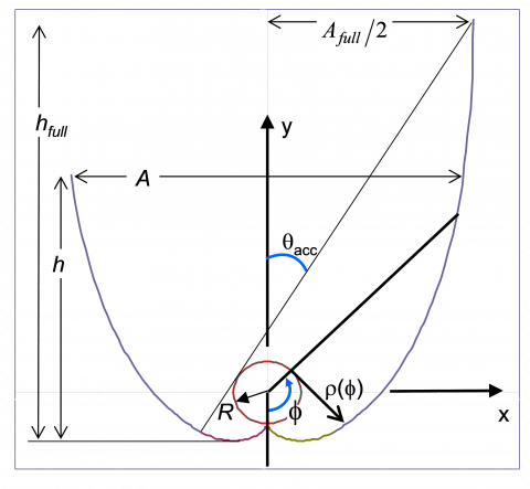
The reflector shape able to cope with a cylindrical receiver has been mathematically described by Mc Intire [15]. Figure 1 shows the reflector surface and the system of coordinates useful for describing the reflector curve function. As mentioned above, the concentrator profile is shaped according to the receiver geometry. In the present case R is the receiver radius, f is the parametric angle from vertical axis y and r(f) is the distance from the circular receiver to the mirror curve as measured along a tangent to the receiver circle. Based on the above geometrical parameters, the reflector profile can be described according to two different functions describing an involute of a circle of radius R and a macrofocal parabola, respectively:
$\rho(\phi)=\left\{\begin{array}{cc}{\frac{R\left[\pi / 2+\phi+\theta_{a c c}-\cos \left(\phi-\theta_{a c c}\right)\right]}{1+\sin \left(\phi-\theta_{a c c}\right)}} \\ {R \phi,} & {|\phi| \leq \theta_{a c c}+\pi / 2}\end{array}\right.$ (1)
The compound concentrator is characterized by its half acceptance angle qacc, which in turn is related to either the (full) height hfull of the CPC or its concentration ratio Cfull through the following relationship:
$h_{f i l l}=R \pi\left(\frac{1}{C_{f u l l} \operatorname{tg}\left(\theta_{c c c}\right)}+0.5+\frac{1}{C_{f u l} \pi}\right)$ (2)
The concentration ratio on the other hand is again a function of the acceptance angle and by definition it is also the ratio between the aperture area and the receiver one. These relationships can be written by introducing an additional parameter, namely the aperture chord A. With reference to Figure 1 and considering a reflector of full height hfull, the concentration ratio Cfull is hence given as:
$C_{f u l l}=\left\{\begin{array}{l}{A_{\text {full}} / 2 \pi R} \\ {1 / \sin \left(\theta_{\text {acc}}\right)}\end{array}\right.$ (3)
With respect to the full height of the complete reflector, in practical applications the mirror is usually truncated in height for compacting its dimensions. This is allowed by the fact that the aperture is slightly increased from a given y value on and further height does not increase meaningfully the aperture.
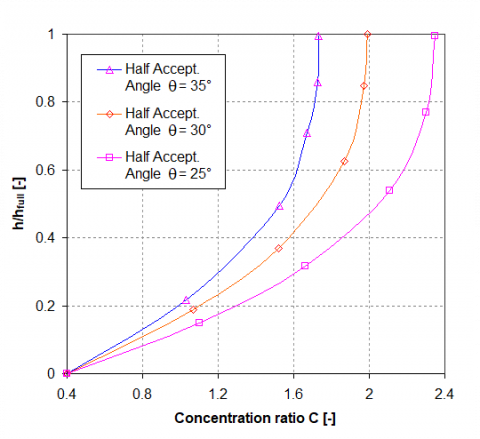
Necessarily a truncated height (here referred as h) implies a decrease in the aperture A and hence a reduction in the concentration ratio. The correction to be applied to the full height concentration Cfull can be estimated from the plane and tubular receiver theories [13, 15]. The results of such an analysis have been here condensed Figure 2 where the real C parameter can be inferred from the truncation ratio h/hfull in the range of acceptance angle value from 25° to 35°.
Figure 1. Compound parabolic reflector geometry for a cylindrical receiver
By applying Equations (1-3), the correction on the concentration ratio available from Figure 3 and finally the slight shape modifications to be applied for y-displaced tubular receivers (Winston et al. [16]) the final mirror coordinates have been calculated. The design of the mirror has been carried out with a series of constraints, basically on concentration ratio and receiver diameter and type. The receiver has been selected among the commercially available evacuated tubes pertaining to the family of the tubular absorbers. The choice was finally addressed to a model having a selective coating onto the outer surface of the inner glass tube at a radius R = 18.5mm. The presence of the outer tube and of the evacuated annular space involves a displacement of the receiver with respect to the mirror cusp which is equal in the present investigation to 3.4 mm.
Figure 2. Concentration ratio and height truncation ratio relationship in the acceptance angle range 25-35°
Figure 3. CPR prototype: calculated profile for a tubular receiver with vertical displacement with respect to involute cusp equal to 3.4 mm
Regarding the aperture angle the objective of the present study was to realize a collector able to sight a wide part of the sky dome and to embrace the altitude variation of the sun during the seasons. Pursuing this goal also an important part of the diffuse radiation can be collected. Based on the span of the declination angle oscillation (±23.45°) an acceptance angle of 31° was selected as a good compromise between interesting concentration ratios and broad view of the sky dome. The h/hfull ratio was finally set to 0.5 to which corresponds (Figure 2) a reduction factor of 0.87 with respect to full height C value of 2.0.
The final reflector profile that have been realized is shown in Figure 3, where it is apparent the displaced position of the tubular absorber.
The CPR coordinates have been employed for realizing the real mirror profile from numerical control machining of a resin block 1.5m in length. The macrofocal profile was coated by solar reflecting film manufactured by Huamao company (datasheet normal reflectance in the 0.3 - 2.2 mm wavelength range equal to 0.9 as weighted average on AM = 1.5 solar radiation spectrum).
A series of tests have been hence carried out as a validation of the mirror expected performance in terms of light reflection onto the target. Figure 4 is a superposition of camera snapshots at different laser entering angles q and entering positions along the x-axis (as defined in Figure 1). In Figure 4 the receiver surface is an acrylic tube whose outer diameter is equal to the absorber circumference of the real evacuated tube. The acrylic tube is displaced from macrofocal bottom cusp, as in the reference design. The pictures show also a rear tube connected to the smoke generator for laser beam visualization. As can be observed the laser beams entering the aperture are able to reach the tubular target at both entering angle extremes. To be noticed (bottom figure, q = 0) that thanks to the very good foil reflectivity also the leftmost laser ray is able to reach the target even multiple (virtually infinite in number) reflections are needed.
Figure 4. CPR prototype: superposition of camera snapshots with laser beams at different entering positions and according two different incidence angles: q = 30° (close to half acceptance angle, top image); q = 0° (bottom figure)
The test equipment is described in full details in [17]. The equipment was originally designed to test the thermal performance of commercial solar collectors. Its extension to concentrating solar collectors requested some modifications. In the present paper, just a short description of the original equipment is given; conversely, more details are reserved to the features of the CPC solar collector.
As discussed in [17], the testing apparatus was designed to follow as far as possible the Standard EN 12975-2 [18]. A scheme of the testing equipment with the CPC solar collector is shown in Figure 5. The original equipment was composed by a hydraulic circuit and a metallic frame, the latter designed to support the solar collector and to set its inclination and orientation. Except for new hydraulic connections to the CPC, the hydraulic circuit is still the one described in [17].
Figure 5. Scheme of the closed loop test equipment: 1 Solar Collector, 2 Pressure Transducer, 3 RTD sensor, 4 Safety Valve, 5 Water Supply, 6 Air Vent, 7 Shut-off Valve, 8 Air Heater, 9 Expansion Tank, 10 By-pass Valve, 11 Pump, 12 Check Valve, 13 Balancing Valve, 14 Drain Valve, 15 Flow Meter, 16 Immersion Thermostat
The different devices and instruments are connected with a thermally insulated copper pipe. From the outlet section of the solar collector, the following elements can be recognized: a pressure and temperature measuring group, a heat exchanger, an expansion vessel, a pump, a check valve, a flow regulation valve, a flowmeter, an inlet pressure and temperature measuring group.
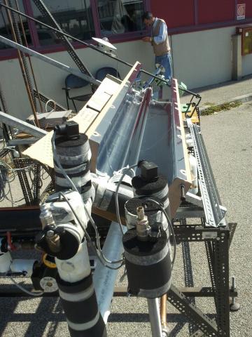
In Figures 6 and 7, two photos of the present prototype of CPC placed on the testing system are shown.
As the typical main feature of a non-imaging reflector, also for low concentration ratios, a tracking system is not required. For the exploitation of this feature, in particular to ensure a wide time window of operation along the year, a proper orientation and tilt is required. The design goal is to guarantee that during almost the whole period of sun radiation the transversal angle, qt, formed between the incident radiation and the normal axis to the aperture surface of the collector, is lower than the half acceptance angle, qacc.
To fulfill this requirement, the test equipment was oriented towards south and the CPC was placed with the single evacuated tube in the E-W direction. The acceptance plane of the CPC reflector was inclined of an angle b = 30°, with respect to the horizontal plane. In this way, being 44.84° N the latitude of the city where the test equipment is located (Ferrara, northern Italy), the CPC solar collector was able to fully intercept the sun radiation along a wide part of the year, except for less than a couple of winter months.
Figure 6. The test equipment with the prototype of CPC (the CPC is still protected by a light blue polymeric film)
Figure 7. The test equipment with the prototype of CPC
The CPC solar collector is composed of a reflector and of a heat extracting system placed inside an evacuated tube. The latter consists of two coaxial cylindrical surfaces, the external one made by high transmittance glass (1.6mm thick) and the internal one by glass with a high absorbance coating. The two glass pipes are separated by the evacuated volume. The evacuated tube has been removed from a commercial solar collector (47mm OD external pipe, 37mm OD internal pipe). The heat extracting system is a U-shaped pipe of new design. This pipe (8mm OD, 6mm ID copper) is in thermal contact with the inner absorber surface by means of springs. The nominal flow rate in the heat extracting system is 20kg/h, typical for these collectors. The heat transfer fluid used during the tests is liquid water.
The inlet and outlet sections of the U-shaped pipe are at the same extremity of the receiver. It follows that both pressure and temperature probes are at the same side of the CPC. Because of their significant weight and of the weakness of the copper pipe, the hydraulic circuit requested a rigid supporting system to avoid damages to the heat extracting system. Some clamps for the connection of the probes to the supporting system were then used.
The global solar irradiance on the acceptance plane of the collector is measured by means of an Eppley Precision Spectral Pyranometer (PSP). The beam irradiance is measured by means of an Eppley Normal Incidence Pyrheliometer (NIP) moved by a solar tracking system Model ST-1. The diffuse solar irradiance is calculated as the difference between the global and the beam solar irradiance.
For the measurement of the flow rate an ultrasonic compact meter Sonometer 1000 model Sharky 773 (Hydrometer) is used. Upstream and downstream the CPC solar collector, two platinum RTD temperature sensors, classified as first class by ASTM 1137-97, are inserted. Finally, the ambient air temperature is measured by means of an armoured thermocouple of the type T.
The whole set of data is acquired with a multimeter Agilent 34970A; the data acquisition is carried out with a Labview software.
The uncertainty characteristics of the single devices used in the measuring system were deeply discussed in [17]. In Par. 5 the overall uncertainty pertaining to the measurements with the present CPC solar thermal collector, will be discussed.
In EN 12975-2 [18] two testing methods are proposed for the measurement of the useful power per unit area extracted from a solar collector:
- Outdoor Steady-State (OSS) test method;
- Outdoor Quasi-Dynamic (OQD) test method.
Although, as explained in Par. 3, the apparatus presents some solutions that deviate from [18], the tests have been carried out as far as possible following the performance test method called "Outdoor steady-state" (OSS).
EN 12975-2 [18] requires that the mass flow rate is kept constant and the inlet temperature is varied; in the present experimental setup the inlet temperature is kept constant and the mass flow rate is varied. For the implications of the present methodology, see [17]. The mass flow rate has been varied over the operating flow range.
Furthermore, in [18] the OSS test method requires some further test conditions to be fulfilled:
- hemispherical solar irradiance: greater than 700 W/m2 at the plane of the collector aperture;
- angle of incidence of direct solar radiation: in the range in which the incidence angle modifier for the collector varies by no more than ± 2 % from its value at normal incidence at the collector aperture;
- diffuse irradiance: lower than 30% of the total irradiance;
- sky conditions: clear;
- air speed: the average value parallel to the collector aperture shall be 3 m/s ± 1 m/s;
- flow rate:
stable to within ± 1 % of the set value during each test;
in accordance to manufacturers specification;
far from the transition region;
- fluid temperature difference: more than 1 K.
The performance of the CPC solar collector is evaluated in terms of instantaneous efficiency, defined as the ratio of the actual useful power extracted to the solar energy intercepted by the collector:
$\eta=\frac{\dot{Q}}{G A}$ (4)
The actual useful power extracted is calculated as:
$\dot{Q}=\dot{m} c_{f}\left(T_{o u t}-T_{i n}\right)$ (5)
where cf is at the mean inlet-outlet temperature:
$T_{m}=\frac{T_{i n}+T_{o u t}}{2}$ (6)
The experimental data of instantaneous efficiency are evaluated at the reduced temperature T*, given by:
$T^{*}=\frac{T_{m}-T_{a}}{G}$ (7)
The couples “experimental data of instantaneous efficiency and reduced temperature”, (T*, h), are interpolated by using the least squares method to obtain the instantaneous efficiency curve. A quadratic polynomial is used:
$\eta=\eta_{0}-a_{1} T^{*}-a_{2} G\left(T^{*}\right)^{2}$ (8)
or, if the quadratic term is not statistically significant:
$\eta=\eta_{0}-a_{1} T^{*}$ (9)
The experimental specific thermal collector output can be finally written as:
$\frac{\dot{Q}}{A}=\eta_{0} G-a_{1}\left(T_{m}-T_{a}\right)-a_{2}\left(T_{m}-T_{a}\right)^{2}$ (10)
or, if the quadratic term is not statistically significant, as:
$\frac{\dot{Q}}{A}=\eta_{0} G-a_{1}\left(T_{m}-T_{a}\right)$ (11)
The main feature characterizing the equipment described in [17] lies in the solution used for conditioning the temperature at the inlet of the test section. This temperature is maintained constantly slightly higher than the ambient temperature with an oversized air-water heat exchanger. Since at the inlet of the solar collector, during the whole time used for testing a collector, the inlet temperature is quite constant, the different values of reduced temperature, Eq. (7), needed for the characterization of the component are obtained by increasing the outlet temperature with an opportune reduction of the flow rate. Minimum and maximum flow rates define the minimum and maximum reduced temperatures, T*.
In an OSS investigation the sun radiation has to be orthogonal to the collector plane or at least inside the acceptance angle, as reported in Par. 4. It was easy to fulfill this requirement in September.
The complete data set of the experimental runs, together with other values of the postprocessing phase useful to characterize the thermal behaviour of the CPC solar collector is reported in Tables 1 and 2.
Eleven tests are available, each of which is represented by the average value of a data set. Since the procedure needs for a steady state and the sun moves continuously, the measurements were carried out 15 min after the attainment of a steady volumetric flow rate. During each data acquisition (5 instruments, 3 readings, appropriate delays), a sampling time of 60 s is requested. This operation is repeated 10 times for each experimental point.
Table 1. Experimental data
|
Test |
G |
Gd |
m |
Tin |
Tout |
Ta |
u |
|
Nr. |
W/m2 |
W/m2 |
kg/h |
°C |
°C |
°C |
m/s |
|
1 |
959.4 |
186.5 |
20.5 |
27.1 |
34.2 |
26.6 |
1.3 |
|
2 |
955.8 |
180.4 |
15.5 |
27.1 |
36.3 |
26.7 |
1.3 |
|
3 |
653.1 |
329.9 |
10.5 |
32.0 |
41.4 |
28.2 |
1.3 |
|
4 |
922.6 |
171.4 |
9.3 |
27.5 |
42.3 |
25.8 |
1.3 |
|
5 |
952.2 |
200.3 |
8.0 |
30.7 |
48.5 |
28.0 |
1.3 |
|
6 |
715.6 |
340.9 |
6. 6 |
32.5 |
47.6 |
28.4 |
1.3 |
|
7 |
911.0 |
181.7 |
6.7 |
36.1 |
56.5 |
24.35 |
1.0 |
|
8 |
888.5 |
158.2 |
5.0 |
27.0 |
53.1 |
25.0 |
1.3 |
|
9 |
845.8 |
223.3 |
4.3 |
34.9 |
61.5 |
23.3 |
1.0 |
|
10 |
966.6 |
162.3 |
2.6 |
28.6 |
78.8 |
23.4 |
1.0 |
|
11 |
822.1 |
335.8 |
2.7 |
33.1 |
73.2 |
27.8 |
1.3 |
Table 2. Calculated values based on experimental data.
|
Test |
Gd/G |
Re |
m/A |
Q/A |
T* |
h |
|
Nr. |
|
|
kg/(hm2) |
W/m2 |
m2K/W |
|
|
1 |
0.194 |
1544 |
66.5 |
550.3 |
0.0043 |
0.574 |
|
2 |
0.189 |
1195 |
50.3 |
538.3 |
0.0053 |
0.563 |
|
3 |
0.505 |
898 |
34.2 |
370.0 |
0.0131 |
0.566 |
|
4 |
0.186 |
760 |
30.0 |
514.4 |
0.0099 |
0.557 |
|
5 |
0.210 |
716 |
25.8 |
533.0 |
0.0122 |
0.560 |
|
6 |
0.476 |
596 |
21.3 |
372.6 |
0.0164 |
0.521 |
|
7 |
0.199 |
680 |
21.7 |
500.5 |
0.0241 |
0.549 |
|
8 |
0.178 |
451 |
16.1 |
488.7 |
0.0169 |
0.550 |
|
9 |
0.264 |
447 |
13.8 |
426.3 |
0.0294 |
0.504 |
|
10 |
0.168 |
295 |
8.4 |
489.2 |
0.0313 |
0.506 |
|
11 |
0.409 |
303 |
8.7 |
404.9 |
0.0308 |
0.493 |
The reference surface of the CPC solar collector chosen for the calculation of efficiency and specific useful power extracted is its aperture area (0.21 x 1.45 m2).
As discussed in Par.3, the standard EN 12975-2 [18] implies some restrictions in the utilization of the experimental data by fixing precise test conditions to be fulfilled. In Table1 some deviations from these rules can be recognized, in particular for the share of diffuse irradiance. In some of the tests (Nr. 3, 6 and 11) the diffuse irradiance is greater than 30% of total irradiance. Furthermore, in Test Nr. 3 the hemispherical solar irradiance is lower than 700 W/m2. The availability of data not exactly fitting the restrictions given by EN 12975-2 [18] for the OSS method, suggested the evaluation of their influence on the efficiency curve. Since this effect was negligible, it was decided for the utilization of the whole set of data.
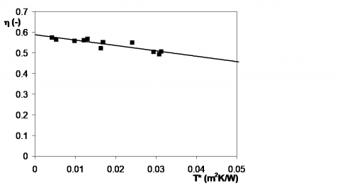
Based on Table 1 data set, the instantaneous efficiency, h, has been calculated and plotted against the reduced temperature difference, T*, as shown in Figure 8. The experimental values of efficiency are available for values of T* in the range 0.004 ≤ T* ≤ 0.032 m2KW-1.
One of the main results of the thermal characterization of a solar collector is its efficiency curve, obtained as an interpolation of the data shown in Figure 8. The standard EN 12975-2 [18] suggests two possible interpolations: linear or quadratic. Since very low values of wind velocity characterize the experimental data set (Table 1), and the experiments are far from the stagnation conditions, the quadratic term of a parabolic interpolation is not statistically relevant. The efficiency curve of our CPC solar thermal collector resulted to be:
$\eta=0.5882-2.571 T^{*}$ (12)
In the data set used for this interpolation, both the dependent variable, efficiency, and the independent one, reduced temperature, are affected by experimental uncertainties. The overall uncertainty, estimated at the 95% confidence level, is calculated using the root-sum-squared propagation rule following the procedure proposed by Moffat [19]. Then the interpolation is performed by considering the uncertainties in both the variables [20].
Figure 8. Efficiency versus reduced temperature difference for the prototype of CPC solar collector
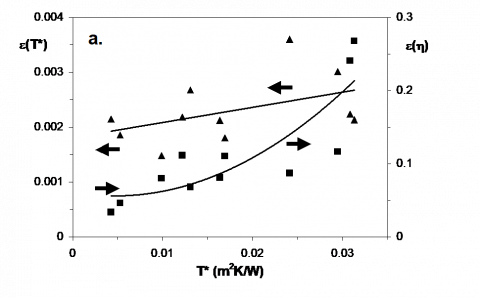
The overall and relative uncertainties of reduced temperature and efficiency are shown in Figure 9 as a function of T*.
The overall uncertainty of the efficiency, e(h), is within 0.033 ≤ e(h) ≤ 0.27 (Figure 9.a), whereas its relative uncertainty is within 0.06 ≤ e(h)/h ≤ 0.53 (Figure 9.b). The overall uncertainty of the reduced temperature difference, e(T*), is within 0.0015 ≤ e(T*) ≤ 0.0036 m2KW-1, (Figure 9.a), whereas its relative uncertainty is within 0.07 ≤ e(T*)/T* ≤ 0.50 (Figure 9.b). The highest relative uncertainties are encountered for the lowest and the highest values of T*, for T* and h, respectively.
While h is quite constant (Figure 8), its absolute uncertainty follows the relative one (Figure 9) and increases with T*. This is due to the flow rate measurement; in the prototype with a single evacuated tube and a low useful power extracted, in order to obtain the highest values of T* very low flow rates are needed, near the bottom end of the measuring range of the flowmeter. In Eq. (5) a high uncertainty in $\dot{m}$ is the reason of a high uncertainty in $\dot{Q}$ and then, through Eq. (4), in h.
On the opposite, the absolute uncertainty for T* is quite constant, about 0.0025 m2K/W. Since T* varies in a range of small values (0.005 ≤ T* ≤ 0.035 m2KW-1), its relative uncertainty becomes high for the lowest values of T*.
The experimental values of specific useful power extracted, $\dot{Q} / A$, are shown in Figure 10 as a function of the temperature difference between mean fluid and ambient temperature, Tm - Ta. By following the standard EN 12975-2 [18], an equation can be written for the above parameter based on the constants given in Eq. (12):
$\frac{\dot{Q}}{A}=0.5882 G-2.571\left(T_{m}-T_{a}\right)$ (13)
A comparison of the experimental values of Table 1 (diamonds) and their theoretical counterparts calculated with Eq. 12 (triangles) shows a very good agreement.
Figure 9. Overall (9.a) and relative uncertainties (9.b) for efficiency and reduced temperature difference, (▲: temperature; ■: efficiency)
Not included in Table 1, two further experimental conditions have been investigated: they refer to a very high value of the diffuse radiation (Gd/G equal to 0.992 and 0.988, respectively) and the corresponding experimental points are shown in Figure 10. A comparison of these data with the predictions of Eq. (13) (empty symbols in Figure 10) shows that also in this limiting case the agreement is very good.
For values of global irradiance equal to G = 600, 800 and 1000 W/m2, the specific collector output, $\dot{Q} / A$, given by Eq. (13) is also reported in Figure 10. Three parallel lines of production are obtained; for fixed values of global solar irradiance, G, and ambient temperature, Ta, these lines show a slowly decreasing trend, when increasing the mean heat transfer fluid temperature. This behaviour is typical of an evacuated tube solar collector characterized by a high level of thermal insulation.
The stagnation temperature of the present prototype was calculated by following Annex C of the standard EN 12975-2 [18]. For the values of ambient temperature and global solar irradiance suggested by the standard (Ta,s = 30°C and Gs = 1000 W/m2) a stagnation temperature Ts = 257.8°C is obtained.
Figure 10. Experimental collector output per unit of aperture area (triangles) compared with the estimations of Eq. (10) (diamonds). Empty symbols refer to overcast sky performance (diffuse radiation is dominant)
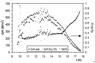
Figure 11. Comparison between experimental and predicted data of thermal production during a full day transient test (D: experimental data for $\dot{Q} / A$; w: predicted data for $\dot{Q} / A$; ○: Gd /G)
The efficiency curve of Eq. (12) is obtained, by following the OSS method of EN 12975-2 [18], with data gathered in relatively short time intervals and in almost steady state conditions. In order to verify this OSS assumption, in Figure 11 we compare the predictions of thermal production given by Eq. (12) with some further experimental data gathered in a day of March. This day is characterized by a global solar irradiance typical of a spring day with clear sky and with limited scattered clouds in the afternoon. The total irradiance is characterized by a peak of 1100 W/m2. The ratio between diffuse and global irradiance was about 0.30 in the morning and 0.4 in the afternoon. In Figure 11 is evident that the predicted values are always higher than the experimental ones. On this point, the literature [21-22] highlights how, for concentrating collectors characterized by significant values of the concentration ratio C, the OSS method could not be considered predictive for a daily estimation.
The main sources of disagreement have to be addressed to the specific trend of the incidence angle modifier for concentrating solar collectors and to the role played by the concentration factor on the performance under diffuse irradiance. A further element of disagreement is the thermal capacity of the concentrating collectors, presumably significant in long time simulations and neglected by the basic approach of the OSS method. For these reasons the OQD method is suggested.
A prototype of CPC solar thermal collector is presented and characterized in its optical and thermal behaviour both theoretically and experimentally.
Its compound parabolic reflector is designed and built based on the theory of the tubular receivers when displaced with respect to the reflector bottom end. The correctness of the design process is demonstrated with a careful preliminary investigation by laser ray tracing.
The Outdoor Steady-State method, as proposed by EN 12975-2 [18], was followed, as far as possible, for the thermal characterization of the present prototype, in particular for the assessment of its instantaneous efficiency curve. The experimental evidence suggests that the validity proposed by the standard [18] can be expanded also to sun conditions with high share of diffuse radiation, at least for the CPC solar thermal collectors.
The efficiency curve based on the quasi-steady conditions required by the OSS method demonstrated not to be reliable when used in daily simulations. For this application some aspects of the dynamic behaviour of the thermal collector and of the collection of the diffuse solar energy seem to deserve further investigations.
The Tema srl company (Genoa, Italy) is acknowledged for its support to the present research.
|
A |
CPC aperture surface (m2) |
|
AM |
air mass coefficient (-) |
|
C |
concentration ratio (-) |
|
cf |
specific heat capacity of heat transfer fluid (kJ/(kgK)) |
|
G |
global solar irradiance (Wm-2) |
|
Gb |
direct solar irradiance (Wm-2) |
|
Gd |
diffuse solar irradiance (Wm-2) |
|
h |
height of the CPC (m) |
|
$\dot{m}$ |
mass flow rate (kg/s) |
|
$\dot{Q}$ |
useful power extracted from collector (W) |
|
R |
receiver radius (m) |
|
Re |
Reynolds number (-) |
|
t |
time (h) |
|
T |
temperature (K) |
|
T* |
reduced temperature difference, Eq. (7), (m2K/W) |
|
u |
surrounding air speed (ms-1) |
|
x |
CPC coordinate parallel to aperture (m) |
|
y |
CPC coordinate perpendicular to aperture (m) |
|
Greek symbols |
|
|
b |
tilt angle of a plane with respect to horizontal |
|
e |
experimental uncertainty |
|
q |
angle |
|
f |
parametric angle from vertical (mirror) axis y |
|
h |
collector efficiency, Eq. (4) |
|
r |
tangential distance from receiver to mirror envelope |
|
Subscripts |
|
|
0 |
zero-loss |
|
a |
ambient |
|
acc |
half acceptance |
|
d |
diffuse |
|
full |
full |
|
in |
inlet |
|
m |
mean |
|
out |
outlet |
|
s |
stagnation |
|
t |
transversal |
[1] Sabiha M.A., Saidur R., Mekhilef S., Mahian O. (2015). Progress and latest developments of evacuated tube solar collectors, Renew. Sustain. Energy Rev., Vol. 51, pp. 1038-1054. DOI: 10.1016/j.rser.2015.07.016
[2] Xu Z.Y., Wang R.Z. (2017). Simulation of solar cooling system based on variable effect LiBr-water absorption chiller, Renewable Energy, Vol. 113, pp. 907-914. DOI: 10.1016/j.renene.2017.06.069
[3] Desai N.B., Bandyopadhyay S. (2016). Thermo-economic comparisons between solar steam Rankine and organic Rankine cycles, Applied Thermal Engineering, Vol. 105, pp. 862-875. DOI: 10.1016/j.applthermaleng.2016.04. 055
[4] Zhang. H., Chen H., Han Y., Liu H., Li M. (2017). Experimental and simulation studies on a novel compound parabolic concentrator, Renewable Energy, Vol. 113, pp. 784-794. DOI: 10.1016/j.renene.2017.06. 044
[5] Abdelhamid M., Widyolar B.K., Jiang L. Winston R. (2016). Novel double-stage high-concentrated solar hybrid photovoltaic/thermal (PV/T) collector with nonimaging optics and GaAs solar cells reflector, Applied Energy, Vol. 182, pp. 68-79. DOI: 10.1016/ j.apenergy.2016. 07.127
[6] Jradi M., Riffat S. (2014). Medium temperature concentrators for solar thermal applications, Int. J. Low-Carbon Techn., Vol. 9, pp. 214–224. DOI: 10.1093/ijlct/ cts068
[7] Bendt P., Rabl A., Gaul H., Reed K. (1979). Optical analysis and optimization of line focus solar collectors, Technical Report, Solar Energy Research Institute, Golden, Colorado (USA).
[8] Hinterberger H., Winston R. (1966). Efficient light coupler for threshold Cernkov counters, Rev. Sci. Instrum, Vol. 37, No. 8, pp. 1094-1095. DOI 10.1063/1.1720428
[9] Xu D.H., Qu M. (2013). Compound parabolic concentrators in solar thermal applications: A review, ASME 2013 7th International Conference on Energy Sustainability, Minneapolis, Minnesota, USA, July 14-19 2013, Paper No. ES2013-18409. DOI: 10.1115/ES2013-18409
[10] Canavarro D., Chaves J., Collares-Pereira M. (2016). A novel Compound Elliptical-type Concentrator for parabolic primaries with tubular receiver, Solar Energy, Vol. 134, pp. 383-391. DOI: 10.1016/j.solener.2016.05. 027
[11] Rabl A., O'Gallagher J., Winston R. (1980). Design and test of non-evacuated solar collectors with compound parabolic concentrators, Solar Energy, Vol. 25 No. 4, pp. 335-351. DOI: 10.1016/0038-092X(80)90346-1
[12] Casano G., Fossa M., Piva S., (2017). Design and experimental characterization of a CPC solar collector, Int J Heat & Tech. Vol. 35, No. Special Issue 1, pp. S179-S185. DOI: 10.18280/ijht.35Sp0125
[13] Rabl A., Goodman N.B., Winston R. (1979). Practical design considerations for CPC solar collectors, Solar Energy, Vol. 22, pp. 373–381. DOI: 10.1016/0038-092X(79) 90192-0
[14] Gallagher J.O. (2008). Non Imaging Optics in Solar Energy, Morgan and Claypool.
[15] Mc Intire W.R. (1979) Truncation of non imaging cusp concentrators, Solar Energy, Vol. 23, pp. 351-355. DOI: 10.1016/0038-092X(79)90130-0
[16] Winston R., Miñano J.C., Benítez P. (2005). Non Imaging Optics, Academic Press.
[17] Casano G., Piva S. (2013). On the measurement of the instantaneous efficiency of solar thermal collectors with a modified EN 12975 test facility. Int J Heat & Tech., Vol. 31, pp. 25-30. DOI: 10.18280/ijht.180108
[18] EN 12975-2. (2006). Thermal solar systems and components - Solar collectors - Part 2: Test methods.
[19] Moffat R.J. (1994). Establishing the credibility of experimental work, Experimental Thermal and Fluid Science. Vol. 8, inside back cover.
[20] Demings W.E. (1943). Statistical Adjustment of Data, New York, Wiley.
[21] Fischer S., Lüpfert E., Müller-Steinhagen H. (2006). Efficiency testing of parabolic trough collectors using the quasi-dynamic test procedure according to the European Standard EN 12975, SolarPACES 13th Symposium on Concentrating Solar power and Chemical Energy Technologies, Sevilla.
[22] Osório T., Carvalho M.J. (2012). Testing of solar thermal collectors under transient conditions, Energy Procedia Vol. 30, pp. 1344-1353. DOI: 10.1016/ j.egypro.2012.11.148