OPEN ACCESS
There are various analyses performed to study the heat transfer performance of nanofluid as working fluid in the heat pipe. The studies include the different viscosity, density, specific heat and thermal conductivity effects. However, to consider in terms of cost of material, high thermal efficiency particle with high concentration, for example, gold and diamond would cost higher even though it shows good thermal performance as compared to other nanoparticles. In this research, an experiment is conducted to investigate the heat transfer characteristics by using low concentrations of diamond water, which is less than 1% in Loop Heat Pipe (LHP). The nanofluid consists of three types of mass concentration which is 0.3%, 0.6% and 0.9%. There are two conditions to study the effect of nanofluid to heat transfer performance on LHP in this experiment. The conditions are different flow rate and different heat load application. The LHP performance is evaluated in terms of total thermal resistance (Rt) of LHP, heat transfer coefficient of evaporator and transient temperature distribution. To justify the experiment, the results were compared with ANSYS simulation, which found in good agreement. The significant gain from this experiment is the ability to prove that low concentration of diamond attains higher heat transfer coefficient than water. At the same time, the bubble flow patterns of diamond water in vapor line are found to be smaller than water which indicate higher heat transfer characteristic for working fluid compared with pure water. Thus, there is a potential for low concentration of diamond water nanofluid to be utilized as working fluid, in terms of cost, than using mass concentration of more than 1%.
heat transfer coefficient, loop heat pipe, nanofluid, total thermal resistance
Over the past decade, nanofluid has been reported to poss higher thermal conductivity than conventional water, as coolant. However, an approach consists in the change of the thermo physical properties of the working fluid was first introduced by Maxwell in 1873 [1], who proposed the addition of solid micro particles to fluid as the thermal conductivity of solids is higher than that of conventional fluids. The resulting mixture has an increased thermal conductivity with respect to the base fluid. Later, the word, nanofluid was introduced by Choi in 1995 [2], who prepared by dispersing nanometer-sized particles, generally less than 100 nm in a base fluid such as water. Then, the concept of nanofluid by applying nanotechnology to improved thermal conductivity was pioneered in Argonne National Laboratory (Illinois, U.S.A.). However, Loop Heat Pipes, LHP were first invented at the Urals Technical University in Russia in 1971. In this particular heat pipe, the evaporator and condenser are separated, with the working fluid transported between the two components via tubing or pipes. LHP was used in space for the thermal management purpose, especially on satellites. Maidanik [3] has introduced the first patent related to a loop heat pipe (LHP) in 1985 by conducting an experiment under various operating temperature and heater power with water based diamond nanofluid in the Loop Heat Pipe. They reported that the nanofluid could effectively enhance heat transfer due to the occurrence of strong oscillatory motion of the flow.
Since the loop heat pipes with nanofluid can provide better cooling capability, there are numerous studies focusing on nanofluid in heat pipes been conducted. In the year 2008, Lin [4] compared 20nm silver nano-fluid at different concentration (100 ppm and 450 ppm) with filling ratio (20%, 40%, 60%, 80%, respectively) in pulsating heat pipe. The thermal resistance of evaporator and condenser was decreased by 7.79°C and 0.092°C/W respectively. In the same year, Naphon Paisarn [5] investigated the enhancement of heat pipe thermal efficiency with TiO2 + alcohol nanofluids. The diameter of TiO2 nanoparticles with 21nm was used. The nanoparticles added to the base fluid had significant effect on the enhancement of thermal efficiency of the heat pipe. For the particular nanofluid with 0.10% nanoparticles volume concentration, the thermal efficiency of heat pipe increased as much as 10.60% compared to that of the based working fluid.
Chandrasekar and Suresh [6] had experimentally investigated the effective thermal conductivities and viscosities of water-based nanofluid containing Al2O3 nanoparticles (Al2O3/water nanofluids). The Al2O3 nanoparticles with an average diameter of 43 nm ran with various volume concentrations from 0.33% to 5%. The measured thermal conductivities of the Al2O3/water nanofluids increased linearly with volume concentration.
Yi-Hsuan Hung [7], studied the effects of charged volume ratio of the working fluid (20%, 40%, 60%, and 80%), tilt angle (10° 40°, 70°, and 90°), heat pipe length, heating power (20W, 30W, and 40W), and weight fraction of with Al2O3/water as nanofluid. The Al2O3/water nanofluid contained approximately 20nm in size served as the working fluid in three concentration (0.5%, 1.0%, and 3.0%) in heat pipes. The results showed that at a heating power of 40W, the optimal thermal performance for Al2O3/water nanofluid heat pipes measuring 0.3m, 0.45m, and 0.6m was 22.7%, 56.3%, and 35.1%, respectively, better than that of pipes using distilled water as the working fluid.
Rosari Saleh [8] performed experimental investigation on the effective thermal conductivities of ethylene glycol-based nanofluid containing low concentration of ZnO nanoparticles from 0.025 to 0.5 vol% nanofluid with average crystallite sizes of nanoparticle 18 and 23 on a screen mesh heat pipe. The experimental data revealed that nanofluid containing a small fraction of nanoparticles had higher thermal conductivities compared to the base fluid. The thermal conductivity increased significantly with increasing volume fraction of nanoparticles, the conductivity ratio showed enhancements of approximately 5.3% until 15.5%.
Ghanbarpour [9], performed experimental investigation and theoretical study on thermal conductivity and viscosity of Al2O3/water nanofluid. The results showed that thermal conductivity improved with the increased in mass fraction and temperature. Another finding in his research was the increment in viscosity is much higher than the increment in thermal conductivity. The thermal conductivity and viscosity enhancement were in the range of 1.1–87% and 18.1–300%, respectively
Gunnasegaran [10] used experimental investigation and finite element simulation to compare the heat transfer performance of a loop heat pipe with different concentrations of SiO2–water with pure water. The test result showed the average decreased of 28%–44% of heat load ranging from 20 W to 100 W in the thermal resistance of LHP using nanofluid as compared with pure water.
Mohammad Hemmat Esfe [11], experimentally studied on thermal conductivity of Magnesium Oxide–water nanofluid with nanoparticles with average diameters of 40 mm in a circular pipe, where the volume fraction of nanoparticles in the base fluid was less than 1% (low concentration). From this experiment, he discovered that the addition of nanoparticles and the increment of Re enhanced the Nusselt number in turbulent flow. The Nusselt number increased by 21.8% at Re = 6700. Further maximum enhancement of heat transfer coefficient was about 35.93% for 1.0% volume fraction of nanofluid at Re = 7331.
Tayfun Menlik [12], experimentally demonstrated the effects of using nano-fluid obtained from MgO to improve the performance of a heat pipe. MgO nanoparticles with average diameters of 40nm were suspended in the base fluid (demonized water). The thermal performance of the MgO containing nano-fluid was better than that of deionized water. The highest improvement in efficiency was determined at 26% with heat load 200W and with condenser coolant flow rate of 7.5g/s.
Wan [13] experimentally investigated the influence of a nanofluid on the thermal characteristics of a specially designed miniature Loop Heat Pipe mLHP and explored the mechanism of heat transfer enhancement of the nanofluid in the mLHP. The nanofluid was composed of deionized water and Cu nanoparticles and had an average diameter of 50 nm. Reductions of 12.8% and 21.7% were achieved in the evaporator wall temperature and total thermal resistance, respectively, while the heat transfer coefficient (HTC) of the evaporator increased 19.5% when substituting the nanofluid with 1.0wt% of deionized water with heat load of 100W.
Trijo Tharayil and Lazarus Godson Asirvatham [14] experimentally analyzed the heat transfer performance of miniature loop heat pipe with graphene–water nanofluid at heat load range of 20–380W in vertical orientation. The graphene nanosheets with 1–5nm thickness in very low volume fractions of 0.003%, 0.006% and 0.009% were mixed with distilled water and this mixture was prepared as nanofluid. The experimental results indicated that this nanofluid improved the thermal performance of the miniature loop heat pipe and lowered the evaporator interface temperature compared to distilled water. The lowest thermal resistance value (0.083K/W at 380W) was observed for the optimum concentration and it was 21.6% below the value of distilled water
Emad Sahinezhad [15] experimentally investigated the heat transfer and the thermal performance of sintered wick heat pipes using graphene nanoplatelets (GNP) nanofluid. The Graphene Nano Particle had a specific surface area of 750m2/g, a thickness of 2nm and a diameter of 2μm. The thermal conductivity of a GNP nanofluid increased with GNP nanoparticle concentration and working temperature. The enhancement ranged between 12% and 28% for the GNP nanofluid concentrations considered.
Based on the outcome of a few studies, it was observed that once the heat pipe operated with nanofluid reached the steady state condition, the heat transfer coefficient for the heat pipe improved, as well as the thermal resistance. Thus, the application of nanofluid as working fluid in Loop Heat Pipe was promising in terms of its cooling efficiency. Nevertheless, diamond nanoparticle still performed better in thermal conductivity than other oxide metal nanoparticle with the reason diamond had an advantage of higher thermal conductivity (about 1000Wm K) than most metals and the colloidal was stable over a period of time with no particle agglomeration. In terms of volume fraction of nanofluid, although nanofluid with higher heat conduction coefficients able to dispel more heat. But the higher concentration will make the higher viscosity and will cause poor heat transfer. [4]. Furthermore to consider in term of cost effective in the current competitive market, it is required to explore the ability of low mass concentration of nanoparticles to gain the maximum heat transfer of LHP system. Owing to this situation, the present study will focus on the low concentration of diamond nanofluid to evaluate the thermal performance of LHP and compare with pure water under different heat load and flow rate.
2.1 Nanofluid preparation
The diamond nanoparticles used for current investigation had an average size of less than 10 nm and a density of 3.5 g/cm3. The nanofluid was prepared by dispersing diamond nanoparticles with different volume concentration in DI water. The particle mass fraction of diamond water nanofluid in the present study was calculated using equation (1) where, amount of diamond water in grams。
% mass fraction = $\frac{W_{n p}}{W_{b f}}$ x 100 % (1)
Where $w_{n p}$ = weight of nanoparticles in gram
$W_{b f}$ =weight of base fluid in gram
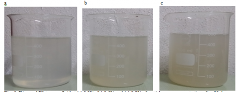
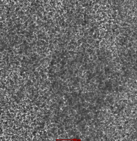
The nanofluid was then stirred with a magnetic stirrer for 1 hr as to ensure uniform dispersion of nanoparticles in the nanofluids. Then, the diamond/DI-water mixture was ultrasonicated using an ultrasonic cleaner (Elma TI-H) for 5 hours continuously. The nanofluid samples were then kept for 1 month to make sure that no particle settlement at the bottom of the beaker. After 1 month, the condition of the nanofluid showed no particle settlement and this condition remained stable as shown in Figure 1. Figure 2 shows the transmission electronic microscope (TEM) images of the dispersed diamond nanoparticles in water with particle mass concentration of 0.3% at magnification- 38kX at room temperature 22°C. It shows that the diamond nanoparticles dispersion is consistent and evenly distributed. The thermo-physical properties of nanofluid such as density, heat capacity, thermal conductivity and viscosity are calculated based on table 1.
Figure 1. Diamond water nanofluid at (a) 0.3%, (b) 0.6% and (c) 0.9% of particle mass concentration after 30 days
Figure 2. TEM images of diamond nanoparticles suspended in DI water
Table 1. Formulas applied for the calculation of nanofluids thermo physical properties
|
Nanofluid Property |
Formula |
|
Density $\rho_{n f}$ |
$(1-\phi) \rho_{b f}+\phi \not \rho_{P}$ (1) |
|
Heat Capacity, $\left(\rho c_{p}\right)_{n f}$ |
$(1-\phi)\left(\rho c_{p}\right)_{n f}+\phi\left(\rho c_{p}\right)_{p}$ (2) |
|
Thermal conductivity $\kappa_{n f}$ |
$\frac{\kappa_{p}+2 \kappa_{b f}+2\left(\kappa_{p}-\kappa_{b f}\right) \phi}{\kappa_{p}+2 \kappa_{b f}-\left(\kappa_{p}-\kappa_{b f}\right) \phi} \kappa_{b f}$ (3) |
|
Dynamic viscosity $\mu_{n f}$ |
$\mu_{b f}(1+2.5 \phi)$ (4) |
In this study, diamond water with mass concentration of 0.3%, 0.6% and 0.9% nanofluid are used to determine the cooling efficiencies of LHP. Table 2 shows the list of thermo physical properties of nanofluid
Table 2. Thermo physical properties of diamond water nanofluid
|
(%) |
$\rho$ (Kgm3) |
$\mu$ (Ns/m2) |
K (W/mK) |
Cp (J/KgK) |
|
0 |
998.20 |
1.003 |
0.613 |
4182 |
|
0.3 |
1005.74 |
1.011 |
0.619 |
4170.95 |
|
0.6 |
1013.27 |
1.018 |
0.624 |
4159.89 |
|
0.9 |
1020.81 |
1.026 |
0.630 |
4148.84 |
2.2 Experimental setup
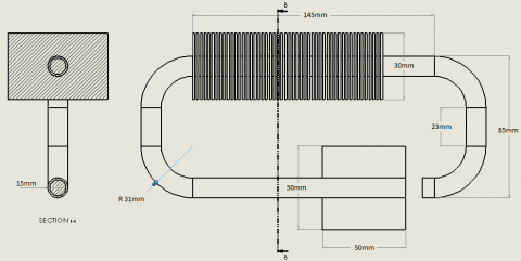
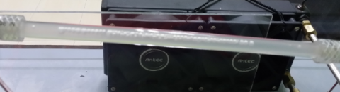
The Loop Heat Pipe in the present experiment is shown in 4. The experimental setup has a flat evaporator, which is combined with the compensation chamber, with a total dimension of 50mm × 50mm × 4mm. A water tank with 0.75 liter glass vessel is used as liquid reservoir and connected to a pump (Longer pump). To observe the phenomena inside the LHP, the vapor line is made of transparent plastic tubes. The other part of the LHP is made of copper. The internal and external diameters of both vapor and liquid lines are 13.5mm and 15mm. The condenser section is made of 50 aluminum rectangular fins and cooled by installing two pieces of long screwed fans. To maintain steady state cooling conditions in the condenser section, the heat load and flow rate of the cooling liquid are fixed at a constant value. The temperatures measured by the K-type thermocouples are collected through a data acquisition (Pico log TC-08) with sample rate of 1Hz and connected to a PC to collect the data. The thermocouples with an accuracy of 1.1C are installed on the pipe/wall in different locations of the loop, including the copper base plate (Tb), the evaporator (Te), the vapor line (Tv), the condenser section (Tc) and the liquid line (Tl). The experiments are conducted under a heating power of 20W and increase it up to 60 W by adjusting the variac from the power supply (W5 Series 30A-720A) whereas the coolant flow rate is adjusted from 5ml per min to 7.5 ml/min, which is controlled by a flow meter knob.
Figure 4. Schematic diagram of experimental setup for loop heat pipe
2.3 Data analysis
The heat flux supply by bottom base plate can be denoted as
$q=\frac{Q}{A_{b}}$ (5)
where Q is the heat input and Ab is the area of base plate.
The total thermal resistance (Rt) of LHP at ambient temperature Ta is the sum of thermal resistance of 5 major component which is thermal resistance of evaporator, thermal resistance of condenser, thermal resistance of vapor line, thermal resistance of liquid line and thermal resistance of heater base as shown in (6).
Rt= Rb + Re + Rv + Rc + Rl (6)
The thermal resistance for copper base plate (Rb) is:
$R_{b}=\frac{T_{b}-T_{e}}{Q}$ (7)
where Tb denotes the temperature at the copper base plate and Ta is the ambient temperature.
The thermal resistance of the evaporator section
$R_{e}=\frac{T_{e}-T_{v}}{Q}$ (8)
where Te is the temperature at evaporator section.
The thermal resistance of the vapor line (Rv) is:
$R_{v}=\frac{T_{v}-T_{c}}{Q}$ (9)
where Tv is the temperature at the vapor line area.
The thermal resistance of the condenser (Rc) is:
$R_{v}=\frac{T_{c}-T_{l}}{Q}$ (10)
where Tc is the temperature at the condenser.
The thermal resistance of the liquid line
$R_{l}=\frac{T_{l}-T_{a}}{Q}$ (11)
where Tl the temperature at the liquid line area.
The heat transfer performance of nanofluid through the LHP was determined in terms of heat transfer coefficient of evaporator in different Reynolds number as shown.
$h_{e}=\frac{Q}{A_{e}\left(T_{e}-T_{a}\right)}$ (12)
where Ae is the surface area of evaporator.
The value of the Reynolds number determines the flow is laminar or turbulent.
$\mathrm{Re}=\frac{\rho v D}{\mu}$ (13)
where D is the inside diameter of the tube (or pipe), υ is the average velocity of the fluid, ρ is the density of the fluid and μ is its dynamic viscosity.
For the entire length of the pipe in the test section through which the nanofluid flowed, the Nusselt number was obtained using the measured values of the local heat transfer coefficient h and the expression Nusselt Number are obtained from Equation (14).
$N u_{n f}=\frac{h_{n f} D}{k_{n f}}$ (14)
where κnf is the thermal conductivity of nanofluid which calculated based on Equation (3).
2.4 Governing equation
The flow in present study is laminar, incompressible flow. Thus, the governing equation for continuity, momentum and energy for the air flow could be expressed from equation 15 until 19:
1.Continuity equation
$\frac{\partial u_{f}}{\partial x}+\frac{\partial v_{f}}{\partial y}+\frac{\partial w_{f}}{\partial z}=0$ (15)
where uf, vf and wf are the fluid velocity, x-, y- and z-axis correspondingly
2.Momentum equation
(x- direction)
$\rho_{f}\left(\frac{\partial u_{f}}{\partial t}+u_{f} \frac{\partial u_{f}}{\partial x}+v_{f} \frac{\partial u_{f}}{\partial y}+w_{f} \frac{\partial u_{f}}{\partial z}\right)=$ $-\frac{\partial P}{\partial x}+\mu_{f}\left(\frac{\partial^{2} u_{f}}{\partial x^{2}}+\frac{\partial^{2} u_{f}}{\partial y^{2}}+\frac{\partial^{2} u_{f}}{\partial z^{2}}\right)+\rho_{f} g_{x}$ (16)
(y- direction)
$\rho_{f}\left(\frac{\partial v_{f}}{\partial t}+u_{f} \frac{\partial v_{f}}{\partial x}+v_{f} \frac{\partial v_{f}}{\partial y}+w_{f} \frac{\partial v_{f}}{\partial z}\right)=$ $-\frac{\partial P}{\partial x}+\mu_{f}\left(\frac{\partial^{2} v_{f}}{\partial x^{2}}+\frac{\partial^{2} v_{f}}{\partial y^{2}}+\frac{\partial^{2} v_{f}}{\partial z^{2}}\right)^{+} \rho_{f} g_{y}$ (17)
(z- direction)
$\rho_{f}\left(\frac{\partial w_{f}}{\partial t}+u_{f} \frac{\partial w_{f}}{\partial x}+v_{f} \frac{\partial w_{f}}{\partial y}+w_{f} \frac{\partial w_{f}}{\partial z}\right)=$ $-\frac{\partial P}{\partial x}+\mu_{f}\left(\frac{\partial^{2} w_{f}}{\partial x^{2}}+\frac{\partial^{2} w_{f}}{\partial y^{2}}+\frac{\partial^{2} w_{f}}{\partial z^{2}}\right)^{+} \rho_{f} g_{z}$ (18)
where $\rho_{f}$ is fluid density, t is the time, P is the pressure, $\mu_{f}$ is fluid viscosity, gx, gy and gz are gravity
3.Energy equation
$\rho_{f} C_{p} \frac{\partial T}{\partial t}+\rho_{f} C_{p}\left(u_{f} \frac{\partial T}{\partial x}+v_{f} \frac{\partial T}{\partial y}+w_{f} \frac{\partial T}{\partial z}\right)=$ $k_{f}\left(\frac{\partial^{2} T}{\partial x^{2}}+\frac{\partial^{2} T}{\partial y^{2}}+\frac{\partial^{2} T}{\partial z^{2}}\right)$ (19)
where T is the temperature, Cp is the specific heat, kf is the thermal conductivity
2.5 FEM simulation
A 2 Dimensional model of the LHP assembly geometry which built by SOLIDWORKS 2014 and exported to ANSYS 15 FLUENT is shown in figure 5. The assembly of LHP consists of a copper base plate at underneath the evaporator, heat pipe with a total length of line 460mm, and condenser with 50 aluminum fins. The pipe with an inner and outer diameter of 13.5mm and 15mm is assumed to be made of copper and water liquid is taken as working fluid flow inside the internal channel of the heat pipe.
Figure 5. Schematic diagram of LHP geometry with dimension
The assembly of LHP is given fine meshing with element edge length of 1mm, forming a total of 234388 Hexahedron elements. The 3D meshed modal is illustrated in Figure 6.
The modeling of LHP is assumed perform under adiabatic condition with no heat losses and the initial temperature was taken at 22°C for the entire simulation. The working fluid is flowing through the inlet of loop heat pipe with fix velocity 7.ml/min and return back outlet with velocity assume to be zero. The heat was supplied from the bottom of the evaporator base with heat flux 16000w/m2 calculated based on equation 9 and the heat was dissipated through the surface of the condenser fins.
Figure 6. The meshed simulation model of LHP
3.1 Effect of Flow rate
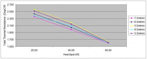
Figure 7. Total thermal resistances (Rt) of LHP versus heat input at different liquid flow rates
Flow rate in LHP plays a major factor to improve the thermal performance of LHP. Thus, it is necessary to identify the optimal flow rate for the LHP in order to achieve maximum heat transfer performance. On the other hand, a fixed flow rate throughout the entire experiment is required to analyze the impact of different heat input to LHP system. Figure 7 illustrates the total thermal resistance, Rt of LHP charged with water at various applied heat input. It is noticed that the increase of liquid flow rate from 5ml/min to 7.5ml/min leads to decrease in Rt of the LHP. The lowest total thermal resistance value achieved are 1.598°C/W at 60W for higher flow rate 7.5ml/min compare to low flow rate 5mlmin of 2.564°C/W at 20W. This means the higher the working fluid flow rate, the better the thermal cooling of LHP. The phenomena can explain with the increase in flow rate, the bubble formation of working flow will deteriorate subsequently cause the phase change to vapor incomplete. Thus, the heat removal becomes efficient as the heat from heating surface to wall evaporator will be carried away along with moving fluid. Hence, the working fluid flow rate 7.5ml/min provide the optimum performance of cooling among other flow rate and is set throughout the entire experiment of thermal analysis.
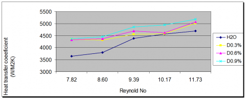
Apart from the influence of flow rate towards the thermal resistance of LHP, the heat transfer coefficient of evaporator shows the increment with the increase of Reynolds number. Figure 8 shows the relationship of heat transfer coefficient (h) of evaporator at various Reynolds numbers under heat input 40W. The results show the heat transfer coefficient increase with the increase of Reynolds number as well as in particle mass concentration. The maximum enhancement of diamond water heat transfer coefficient by 16.7% was noticed at Reynolds number 7.82 whereas the largest heat transfer coefficient 5177W/m2 K was obtained at 60W for 0.9% mass concentration diamond water. This is due to the fact that, with the increase in Reynolds number that leads to the increase in fluid velocity, the heat bubbles do not have enough time to reach to their maximum size, resulting in leaving the heating surface sooner.
Figure 8. Heat transfer coefficient for LHP with different Reynolds numbers
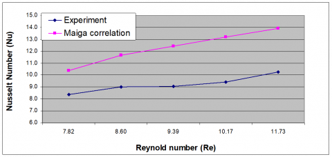
The current fluid flow in this study is assumed as laminar flows. Therefore, a comparison between experiment data with Maiga [16] laminar flow numerical equation was determined.
$\mathrm{Nu}=0.28 \mathrm{Re}_{n f}^{0.35} \mathrm{Pr}_{n f}^{0.4}$ (20)
Figure 9. Comparison between measured nusselts number and Maiga prediction Nusselt number for 0.6% diamond water nanofluid
Figure 9 shows the comparison between measured nusselts number and Maiga prediction Nusselt number for 0.6% diamond water nanofluid. As can be seen from Figure 8, the nusellt number from the experiment is parallel with the numerical prediction by Maiga.
3.2 Effect of heat load
The impact of different heat input to LHP with low concentration of diamond water as working fluid would determine the effectiveness of nanofluid to cool the entire LHP system as compared to conventional working fluid such as water. The higher heat load applied would simulate the actual operating system such as running computer processors, or other industrial heat generation application. Figure 10 states the temperature of the evaporator at heat load 40W and fixed flow rate of 7.5mlmin. As expected, the temperature of the evaporator in the LHP with diamond water nanofluid is lower than the temperature of the evaporator with water after reaching steady state. From the evaporator temperature comparison of different nanofluid’s mass concentration, 0.9% mass concentration of diamond water has the lowest evaporator temperature of 75.97°C while water has the highest evaporator temperature of 81.59°C. A maximum decrease of 6.89% temperature was observed in diamond water with 0.9% mass concentration compared with water at heat load 40W due to the nanoparticles suspension in the nanofluid has a significant effect on the enhancement of heat transfer for its higher heat capacity and higher thermal conductivity of working fluid. [12] Therefore, the heat pipe thermal efficiency heat pipe increases with nanofluids as compared to that of the base working fluids such as water.
Figure 10. Evaporator temperature of LHP with different heat load for different mass concentration of diamond water at heat load 40W and flow rate 7.5ml/min
Figure 11 shows the relationship of total thermal resistance (Rt) of LHP at various applied heat loads. From the graph, it is noticed that the Rt of LHP for both working fluids become smaller as the heat load increases. For heat load of 60 W, the maximum total thermal resistances are 2.353 °C/W for pure water while minimum total thermal resistance are 1.509 °C/W for 0.9% diamond water nanofluid at heat load 20W, respectively. Yet, another observation from the graph show that the diamond water nanofluids Rt at all heat loads are smaller compared to pure water. The total thermal resistance recorded a percentage reduction of 4.75-8.25% can be seen between nanofluid to conventional working fluid at various heat loads. This is due to the suspended nanoparticles in a fluid flow can increase the thermal conductivity of fluid and convective heat transfer from fluid flow to the wall and, which results in the reduction of total thermal resistance of the LHP. Based on test results obtained, it is showing the heat load ranging from 20W to 60W has a significant effect on the Rt LHP system and the diamond water nanofluid has advantages over conventional working fluid water as cooling fluid although with low mass concentration.
Figure 11. Total thermal resistance of LHP with different heat load for different mass concentration of diamond water
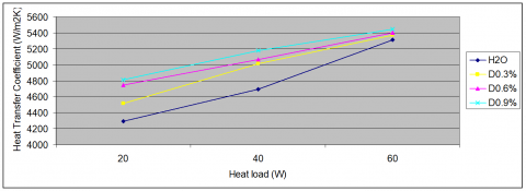
Figure 12 shows the influence of heat load to heat transfer coefficient of evaporator for different mass concentration of diamond water. The maximum improvement of 6.89% was achieved for mass concentration of 0.9% diamond water compare to base fluid water at heat load 20W. Meanwhile the largest heat transfer coefficient obtained is 5366 W/ $m^{2}$ K at 60W for 0.9% diamond water. Based on the observation, it is noticed that the heat transfer coefficient is increased with more nanoparticle for every heat load due to nanopaticle has higher thermal conductivity compared with water. This shows that the cooling of LHP system can be improved by replacing conventional water with nanofluid even with low concentration of nanoparticles.
Figure 12. Heat transfer coefficient of evaporator for different mass concentration of diamond water at flow rate 7.5ml/min
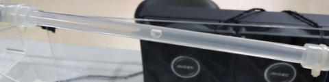
3.3 Flow pattern of nanofluid in vapor line
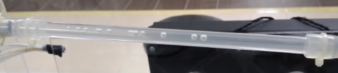
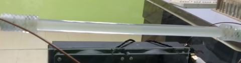
The visualization of flow pattern gives a picture to determine the different heat transfer performance of working fluid in LHP. Hence, an experimental setup was with glass tube along the vapor line in order to capture the flow pattern of working fluid. A Samsung 95000 Galaxy note 3 camera was used as the image recorder to capture the bubble formation with the increasing heat input from evaporator with different working fluid which is water and low concentration of diamond water nanofluid.
Figure 13 shows the effect of 3 different heat input ranging from 20W, 40W and 60W on the flow pattern in the vapor line for pure water charged loop heat pipe. Three different flow patterns are observed in the vapor line with a small heating input of 20W, there is bubble flow inside the vapor line shown in Figure 11 (a). While with the heat input increasing to 40W, the increase in nucleation bubble formed is observed, as shown in Figure 11(b). Finally, a slug flow is appeared in the vapor line in a larger heat input 60W, as shown in Figure 11 (c).
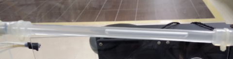
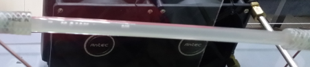
Meanwhile, Figure 14 illustrates the effect of heat input to the flow pattern in the vapor line for 0.6% mass concentration of diamond H20 nanofluid charged in LHP. There is mostly no bubbles formation flow inside the vapor line with the heat input 20W as shown in Figure 12 (a) while heat load increase to 40W, there is a tiny bubble forming in Figure 12(b). Finally a continuous bubbly flow appeared inside the vapor line in a larger heat input of 60W as shown in Figure 12(c). From the obtained results, it shows that the nucleation size formed in the vapor line of LHP charged with diamond-H2O naofluids are smaller than LHP charged with water for all the applied heat input. This is due to the addition of nanoparticles lead to collision with large bubble with intend to bombard the vapor bubble during vaporization which make the bubble is smaller than conventional water.
(a)Bubbly flow at 20W
(b) Continuous Bubbly flow at 40W
(c)Slug flow at 60W
Figure 13. Different flow patterns inside the vapor line. For water (a) Bubbly flow at 20W. (b) Bubbly flow at 40W. (c) Slug flow at 60W
(a)No pattern observed at 20W
(b) Small bubbly flow at 40W
(c) Continuous bubbly flow at 60W
Figure 14. Different flow patterns inside the vapor line. For diamond –H2O with mass concentration of 0.6% nanofluid
3.4 Transient temperature distribution
(a)
(b)
(c)
(d)
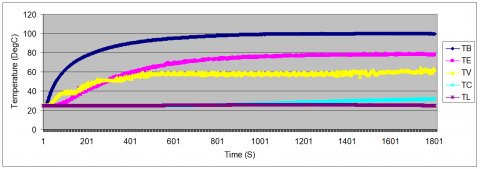
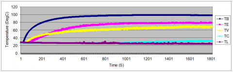
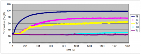
Figure 15. Transient temperature of mass concentrations of diamond water 0% (a), 0.3 %(b), 0.6 %(c), 0.9 %(d) at heat load 40W
The transient temperature distribution of LHP at different mass concentration which includes 0% (Pure water), 0.3%, 0.6% and 0.9% of diamond water nanofluid respectively for heat load of 40W is displayed in Figure 15. Generally, the average decrease of 9-16% in delta T of LHP at mass concentration ranging from 0.3% to 0.9% charged with diamond water nanofluid compared with water (0%) for heat input of 40W. The maximum decrease of 9°C is observed for mass concentrations of 0% to 0.9%. On the other observation, the LHP charged with diamond-H2O nanofluid reached a steady state faster than pure water for all mass concentrations where higher mass concentration 0.9% reach faster at 940s follow by mass concentration of 0.6% reach at 970s and mass concentration of 0.3% reach at 1150s. Meanwhile the water temperatures of all points become steady at 1200s. The steady state is expected to reach faster with nanofluid as the heat transfer is higher for nanofluid than pure water. Thus, the addition of diamond nanoparticles to base water improved the thermal performance of LHP.
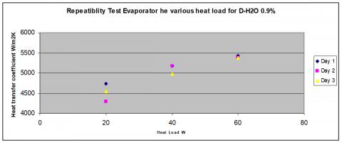
3.5 Repeatability test
A repeatability test was conducted for LHP with mass concentration of 0.9% diamond water nanofluid under flow rate 7.5ml/min. The repeating measurement results are shown in Figure 16 for the different heat transfer coefficient from both graph observation, the repeatability deviation for heat transfer coefficient falls in the range of 0 to 5.8%., which conclude the experiment results for entire study are stable.
Figure 16. Repeatability test for evaporator heat transfer coefficient for working fluid 0.9% diamond water with 3 repeating measurement
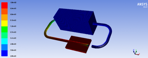
3.6 FEM Simulation results
(a)
(b)
Figure 17. Temperature contour of LHP using pure water (a) and 0.6% diamond –H2O nanofluid at Q = 40 W
The simulation in current study is performed on FEM software package, ANSYS FLUENT in order to verify the experiment results. The thermo physical properties for each mass concentration diamond-H2O nanofluid flow are calculated based on equation from table 1 and listed in table 2 accordingly. The simulated temperature distribution of LHP charged with pure water and 0.6% diamond water is shown in Figure 17.
Table 3 summarizes the comparison between experimental and simulation results for LHP using pure water and diamond water nanofluid with mass concentration of 0.6% at 40W of heat load. As can be seen from the table 4.2, the error between simulation temperature and experimental temperatures are found less than 5%, which indicate the validity of the present experiment for thermal analysis of nanofluid in LHP.
Table 3. Comparison of experimental and simulation temperatures
|
Temperature |
Pure Water |
0.6% Diamond water |
||
|
Exp (°C) |
Simulation (°C) |
Exp (°C) |
Simulation (°C) |
|
|
Tb |
109.47 |
109.32 |
104.22 |
104.38 |
|
Te |
98.69 |
96.93 |
86.51 |
84.93 |
|
Tv |
81.21 |
80.43 |
75.54 |
73.30 |
|
Tc |
30.98 |
30.93 |
27.01 |
26.81 |
|
Tl |
26.81 |
26.91 |
26.61 |
26.81 |
An experiment was performed to investigate the heat transfer characteristics by using low concentration of diamond water in Loop Heat Pipe (LHP). There were two change conditions in the present experiment, the flow rate change and the heat load change. Both change conditions showed that the total thermal resistance of LHP decreased with an increased in flow rate and heat load. As for the heat transfer coefficient, both change conditions produced the same increasing trend with an increase in Reynolds number and heat load. However, the effect of flow rate produced higher thermal performance compared to heat load analysis. The maximum increment of heat transfer coefficient achieved was 16.7% for flow rate change while the heat transfer coefficient improved about 10.95% for heat load change. It was observed that the fluid flow patterns of diamond water in the vapor line were having smaller bubble size compared to pure water bubble with different heat load. This was due to the presence of nanoparticles that bombarded the vapor bubbles during vaporization. In terms of how fast steady state condition could be reached with the same flow rate and heat load, higher mass concentration nanoparticles performed better than water. Hence, the use of low concentration diamond water as coolant was more efficient than conventional water. In addition, the experimental results were compared with ANSYS simulation, and both were found in good agreement.
The author would like to express gratitude to the School of Aerospace, University Sains Malaysia for providing facilities and Ministry of Higher Education (MOHE) for provision of grant with code no 20160103FRGS to support this work.
|
$A$ |
Area [ $m^{2}$ ] |
|
$A_{b}$ |
Area of base Plate [ $m^{2}$ ] |
|
$C_{p}$ |
Specific heat, [J/kg·K] |
|
$h_{e}$ |
Heat transfer coefficient of evaporator, [ $\mathrm{W} m^{2} K$ ] |
|
$Q$ |
Heat input [W] |
|
$q$ |
Heat flux [ $\mathrm{W} / \mathrm{m}^{2}$ ] |
|
$Q^{*}$ |
Flow rate [ $m^{3} / \mathrm{s}$ ] |
|
$R$ |
Thermal resistance [ $^{0} C / W$ ] |
|
$R_{b}$ |
Base thermal resistance [ $^{0} C / W$ ] |
|
$R_{C}$ |
Convective thermal resistance [ $^{0} C / W$ ] |
|
$R_{e}$ |
Evaporator thermal resistance [ $^{0} C / W$ ] |
|
$R_{V}$ |
Vapor line thermal resistance [ $^{0} C / W$ ] |
|
$R_{l}$ |
Liquid line thermal resistance [ $^{0} C / W$ ] |
|
$R_{t}$ |
Total thermal resistance [ $^{0} C / W$ ] |
|
Re |
Reynolds number |
|
Nu |
Nusselt number |
|
Pr |
Prandtl number |
|
T |
Temperature [ $^{0} \mathrm{C}$ ] |
|
$T_{a}$ |
Ambient Temperature [ $^{0} \mathrm{C}$ ] |
|
$T_{b}$ |
Base plate Temperature [ $^{0} \mathrm{C}$ ] |
|
$T c$ |
Condenser Temperature [ $^{0} \mathrm{C}$ ] |
|
Te |
Evaporator Temperature [ $^{0} \mathrm{C}$ ] |
|
$T v$ |
Vapor line Temperature [ $^{0} \mathrm{C}$ ] |
|
$T_{l}$ |
Liquid line Temperature [ $^{0} \mathrm{C}$ ] |
|
t |
Time [s] |
|
$w_{m p}$ |
Weight of nanoparticles [g] |
|
$w_{b f}$ |
Weight of base fluid [g] |
|
$m$ |
Flow rate [ml/min] |
|
Greek Symbols |
|
|
$\mu$ |
Dynamic viscosity, [ $\mathrm{Ns} / \mathrm{m}^{2}$ ] |
|
$\rho$ |
Density [ $\mathrm{kg} / \mathrm{m}^{3}$ ] |
[1] Yu W., Choi S.U.S. (2003). The role of interfacial layers in the enhanced thermal conductivity of nanofluids: A review renovated Maxwell model, Journal of Nanoparticle Research, Vol. 5, pp. 167-171.
[2] Choi S.U.S., Eastman J.A. (1995). Enhancing thermal conductivity of fluids with nanoparticles, in: D.A. Siginer, H.P. Wang (Eds.), Developments and Applications of Non-Newtonian Flows, ASME, pp. 99-105.
[3] Yu F., Maydanik (2005). Loop heat pipes, Appl. Therm. Eng., Vol. 25, pp. 635-657.
[4] Lin Y.H., Kang S.W., Chen H.L. (2008). Effect of silver nanofluid on pulsating heat pipe thermal performance, Appl Therm Eng., Vol. 28, pp. 1312-1317.
[5] Naphon P., Assadamongkol P. (2008). Terrapin Barrack, - Experimental investigation of titanium nan fluids on the heat pipe thermal efficiency, International Communications in Heat and Mass Transfer, Vol. 35, pp. 1316-1319.
[6] Chandrasekar, Suresh S. (2010). Experimental investigations and theoretical determination of thermal conductivity and viscosity of Al2O3/water nanofluid, Experimental Thermal and Fluid Science, Vol. 34, pp. 210-216.
[7] Hung Y.H. (2013). Evaluation of the thermal performance of a heat pipe using alumina nanofluids, Experimental Thermal and Fluid Science, Vol. 44, pp. 508-510.
[8] Saleh R. (2013). Experimental investigation of thermal conductivity and heat pipe thermal performance of ZnO nanofluids, International Journal of Thermal Sciences, Vol. 63, pp. 125-132.
[9] Ghanbarpour (2014). Thermal properties and rheological behavior of water based Al2O3 nanofluid as a heat transfer fluid, Experimental Thermal and Fluid Science, Vol. 53, pp. 227-235.
[10] Gunnasegaran P., Abdullah M.Z., Shuaib N.H. (2013). Influence of nanofluid on heat transfer in a loop heat pipe, Int. Commun. Heat Mass Transfer, Vol. 47, pp. 82-91.
[11] Mohammad H.E. (2013). Experimental studies on the convective heat transfer performance and thermophysical properties of MgO–water nanofluid under turbulent flow, Experimental Thermal and Fluid Science, Vol. 53, pp. 77-78.
[12] Menlik T. (2014). Heat transfer enhancement using MgO/water nanofluid in heat pipe, Journal of the Energy Institute, pp. 1-11.
[13] Wan Z., Deng J., Li B., Xu Y., Wang X., Tang Y. (2015). Thermal performance of a miniature loop heat pipe using water–copper nanofluid, Appl.Therm.Eng., Vol. 78, pp. 712-719.
[14] Tharayil T., Asirvatham L.G., Ravindran V., Wongwises S. (2015). Thermal performance of miniature loop heat pipe with graphene–water nanofluid, International Journal of heat and mass transfer, pp. 965-966.
[15] Sadeghinezhad E., Mohammad M., Rosen M.A., Akhiani A.R., Latibari S.T., Mehralid M., Metselaar H.S.C. (2016). Experimental investigation of the effect of graphene nanofluids on heat pipe thermal performance, Applied Thermal Engineering, pp. 780-784.
[16] Maiga S.E.B., Palm S.J., Nguyan C.T., Roy G, Galanis N. (2005). Heat transfer enhancement by using nanofluid in fored convection flow, Int. J. of Heat and Flow, Vol. 26, pp. 530-546.