OPEN ACCESS
In present day shell and tube heat exchanger is the most common type heat exchanger widely used in oil refinery and other large chemical process, because it suits high pressure application. The aim of this work is to design of shell and tube type heat exchanger with helical baffle and comparing with straight baffle with CFD analysis using ANSYS FLUINT software tools. The model contains 7 Copper tubes each having 20 mm external diameter and 17 mm internal diameter, length 600 mm and inner diameter of steel shell is 90 mm and outer diameter 110 mm. 7 tubes are hold by 6 straight or helical aluminium baffle and the helix angle of baffle is varying from 0º to 30º. All the models are design by using CATIA software tools. In this paper how the pressure drop and overall heat transfer coefficient varies due to different helix angle has been studied when the flow rate remain same. The flow pattern in the shell side of the heat exchanger with continuous helical baffles are forced to be rotational and helical due to the geometry of the continuous helical baffles, which results in a significant increase in heat transfer coefficient per unit pressure drop in the heat exchanger.
helical baffles, helix angle, shell and tube heat exchanger, overall heat transfer coefficient, pressure drop
A Heat Exchanger may be defined as an equipment which transfers energy from a hot fluid to a cold fluid, either maximum or minimum rate within minimum investment and running cost. In this process never two fluids mixed with each other.
This device provides a flow of thermal energy between two or more fluids at different temperatures. Shell and tube heat exchangers are most versatile type of heat exchanger; they use in a wide variety of engineering applications like power generation, waste heat recovery, manufacturing industry, air-conditioning, refrigeration, space applications, petrochemical industries etc.
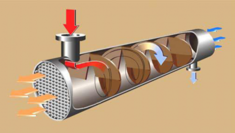
Shell and tube type heat exchanger (STHE) consists of bundle of tubes enclosed in cylindrical shell, one fluid pass through the tubes and second fluid flows between the tube and shells. Most commonly used STHE have large heat transfer efficiency in comparison with others. Shell and tube heat exchangers with segmental straight baffles have low heat transfer Co-efficient due to the segmental straight baffle arrangement causing high leakage flow by passing through the heat transfer surface and high pressure drop that causes a big problem for industries as the pumping costs increases. A simple shell and tube heat exchanger with straight baffle diagram is shown in Figure 1.
Figure 1. A simple shell and tube type heat exchanger
The developments for shell and tube exchangers focus on better conversion of pressure drop into heat transfer i.e. higher Heat transfer co-efficient to drop ratio, by improving the conventional baffle design. With single segmental straight baffles, most of the overall pressure drop is wasted in changing the direction of flow. This kind of baffle arrangement also leads to deathlier undesirable effects such as dead spots or zones of recirculation which can cause increased fouling, high leakage flow that bypasses the heat transfer surface giving rise to lesser heat transfer co-efficient and large cross flow. The cross flow not only reduces the mean temperature difference but it can also cause potentially damaging tube vibration.
Baffle is a device used to put down the flow of a fluid, gas etc. Baffles serve two important functions. They support the tubes during assembly and operation and help prevent vibration from flow induced eddies and direct the shell side fluid back and forth across the tube bundle to provide effective velocity and Heat Transfer rates. The diameter of the baffle must be slightly less than the shell inside diameter to allow assembly, but must be close enough to avoid the significant performance penalty caused by fluid bypass around the baffles.
Shell roundness is important to achieve effective sealing against excessive bypass. Baffles can be made from a variety of materials compatible with the shell side fluid. They can be punched or machined. Some baffles are made by a punch which provides a lip around the tube hole to provide more surfaces against the tube and eliminate tube wall cutting from the baffle edge.
Baffles may be classified as transverse and longitudinal types. The purpose of longitudinal baffles is to control the overall flow direction of the shell fluid such that a desired overall flow arrangement of the two fluid streams is achieved. For example, two-pass shell with longitudinal baffle, split flow, double split flow. Transverse baffles may be classified as plate baffles and grid. Plate baffles may be single segmental, double-segmental, and triple-segmental, non-tubes-in-window segmental baffle and disk-and-doughnut baffle.
4.1 Helical baffle exchanger
The Helical Baffle Heat Exchanger is also known as a Helix changer solution that removes many of the deficiencies of Segmental Baffle Heat Exchanger. It is very effective where heat exchanger is predicted to be faced with vibration condition Quadrant shaped baffle segment are arranged right angle to the tube axis in a sequential pattern that guide the shell side flow in a helical path over the tube bundle. The Helical flow provides the necessary characteristics to reduce flow dispersion and generate near plug flow conditions. The shell side flow configuration offers a very high conversion of pressure drop to heat transfer. Advantages over segmental STHE are increased heat transfer rate, reduced bypass effects, reduced Shell Fouling Factor, Prevention of flow induced vibration & Reduces Pumping cost. Shell and tube type heat exchanger with helical baffle diagram is shown in Figure 2.
Figure 2. Shell and tube type heat exchanger with helical baffle
4.2 Baffle spacing
Baffle spacing is the centerline to-centerline distance between adjacent baffles. It is the most vital parameter in STHE design. The TEMA standards specify the minimum baffle spacing as one-fifth of the shell inside diameter or 50.8 mm, whichever is greater. Closer spacing will result in poor bundle penetration by the shell side fluid and difficulty in mechanically cleaning the outsides of the tubes.
4.3 Literature review
The subject of baffle in shell and tube heat exchanger (STHE) has a wide variety of processes. A large number of works has been published regarding STHE which depicts various factors affecting the thermal efficiency of the STHE. On the basis of that a brief summary is reviewed as follows:
Rajiv Mukherjee [1] explains the basics of exchanger thermal design, covering such topics as:
STHE components; classification of STHEs according to construction and according to service; data needed for thermal design; tube side design; shell side design, including tube layout, baffling, and shell side pressure drop; and mean temperature difference. The basic equations for tube side and shell side heat transfer and pressure drop. Correlations for optimal condition are also focused and explained with some tabulated data. This paper gives overall idea to design optimal shell and tube heat exchanger. The optimized thermal design can be done by sophisticated computer software however a good understanding of the underlying principles of exchanger designs needed to use this software effectively.
M. Serna and A. Jimenez, [2] they have presented a compact formulation to relate the shell-side pressure drop with the exchanger area and the film coefficient based on the full Bell–Delaware method. In addition to the derivation of the shell side compact expression, they have developed a compact pressure drop equation for the tube-side stream, which accounts for both straight pressure drops and return losses. They have shown how the compact formulations can be used within an efficient design algorithm. They have found a satisfactory performance of the proposed algorithms over the entire geometry range of single phase, shell and tube heat exchangers.
Lei et al. [3] have showed the effects of baffle inclination angle on flow and heat transfer of a heat exchanger with helical baffles, where the helical baffles are separated into inner and outer parts along the radial direction of the shell. While both the inner and outer helical baffles baffle the flow consistently, smoothly and gently, and direct flow in a helical fashion so as to increase heat transfer rate and decrease pressure drop and impact vibrations, the outer helical baffle becomes easier to manufacture due to its relatively large diameter of inner edge.
Lutcha and Nemcansky [4] have done experiments to the improvement of tubular heat exchangers with helical baffles for investigation of the flow field patterns generated by various helix angles which is expected to decline pressure at shell side and increase heat transfer process significantly.
Pardeep Kumar et al. [5] experimental investigation has been carried-out to know the thermal performance of Helix exchanger with plain copper tubes or with grooved copper tubes of same size and specification by using co-current flow. During this experimental investigation attempts were made for both exchangers at same operating conditions and it was found that grooved copper tubes helix changer have a better thermal performance as compared to plain copper tubes helix changer at a particular angle, 25̊.
Sunilkumar Shinde et al. [6] were done analyses the conventional segmental baffle heat exchanger by using the Kern method with varied shell side flow rates. They evaluated form their results high heat transfer Co-efficient and lower pressure drop are more effectively obtained in a helix changer. The flow pattern in the shell side of the continuous helical baffle heat exchanger is rotational & helical due to the geometry of continuous helical baffles results in significant increase in heat transfer coefficient.
4.4 Data collection
Table 1. Geometrical parameters of model heat exchanger
|
Sl. No. |
Description |
Value |
Unit |
|
1. |
Shell Inner Diameter, Dis |
0.090 |
m |
|
2. |
Shell Outer Diameter, Dos |
0.110 |
m |
|
3. |
Shell Length, Ls |
0.600 |
m |
|
4. |
Coolant Inlet and Outlet Distance from The Center of Shell, L1 & L2 |
0.270 |
m |
|
5. |
Coolant Inlet and Outlet Pipe Internal Diameter, (Di)P |
0.025 |
m |
|
6. |
Coolant Inlet and Outlet Pipe External Diameter, (Do)P |
0.029 |
m |
|
7. |
Coolant Inlet and Outlet Pipe Length from The Surface of The Shell, LP |
0.030 |
m |
|
8. |
Side Cover Plate Diameter, DSp |
0.090 |
m |
|
9. |
Side Cover Plate Thickness, Ts |
0.020 |
m |
|
10. |
Tube length, lt |
0.600 |
m |
|
11. |
Tube inner diameter, dit |
0.017 |
m |
|
12. |
Tube outer Diameter, dot |
0.020 |
m |
|
13. |
Number of tubes, Nt |
7 |
- |
|
14. |
Tube Pitch, Pt |
0.025 |
m |
|
15. |
Baffle inclination angle, Ɵ |
0-30 |
Deg. |
|
16. |
Baffle Thickness, ΔBT |
0.015 |
m |
|
17. |
Chord height of the baffle hb |
0.010 |
m |
|
18. |
Baffle spacing, B |
0.0671 |
m |
Note: 1. The material of the Shell is made up of Steel,
2. The material of the Tube is made up of couper,
3. The material used in Baffle is Aluminium,
4. The material used in Side Plate cover is Steel, and
5. Hot and cold fluid used as a water in STHE etc.]
Table 2. Properties of the used materials
|
Sl. No. |
Description |
Value |
Unit |
|
1. |
Rate of Discharge in Shell Side, Qs |
0.0089 |
m3/ sec |
|
2. |
Density of the Entrance Liquid in the Shell Side, ρs |
998 |
Kg/m3 |
|
3. |
Density of the Entrance Liquid in the Tube Side, ρt |
974 |
Kg/m3 |
|
4. |
Dynamic Viscosity of the Shell Side (µs) at 25° c |
8.9 x 10⁻⁴ |
Pa.Sec |
|
5. |
Dynamic Viscosity of the Tube Side (µt) At 80° C |
3.6363 x 10⁻⁴ |
Pa.Sec |
|
6. |
Dynamic Viscosity Constant for Shell and Tube Type Heat Exchanger, Φs |
1.1335 |
-- |
|
7. |
Thermal Conductivity of the Shell Material, Ks |
0.6129 |
W/mK |
|
8. |
Thermal Conductivity of the Tube Material, Ks |
0.6687 |
W/mK |
|
9. |
Hot Fluid Velocity at Tube, Vt |
1.4 |
m/sec. |
|
10. |
Cold Fluid Velocity at Shell, VS |
18 |
m/sec. |
|
11. |
Prandtl Number of water, Pr at 80°c |
2.22 |
-- |
|
12. |
Shell Inlet Temperature |
298 |
K |
|
13. |
Tube Inlet Temperature |
353 |
K |
C = Pt - Dot
= 0.025-0.020
= 0.005 m
AS = (Dis x C x B) / Pt
= (0.09 x 0.005 x 0.067143) / 0.025
= 1.2086 x 10⁻³ m2
DE = 4 [( $P_{t}^{2}$ x $\frac{\sqrt{3}}{4}$ ) – ( $\mathrm{d}_{\mathrm{ot}}^{2}$ x $\frac{\pi}{8}$ )] / [πdot / 2]
= 4 [(0.0252 x $\frac{\sqrt{3}}{4}$ ) – (0.022 x $\frac{\pi}{8}$ )] / [ $\frac{\pi}{2}$ x 0.02]
= 1.4458 x 10⁻² m
Vmax = Qs / A
= Qs / ( $\frac{\pi}{4}$ x Dis)
= $\frac{0.0089 \times 4}{\pi \times 0.09^{2}}$ = 1.39899 m/sec
Re = ρ x Vmax x $\frac{D_{E}}{\mu_{s}}$
= (998 x 1.39899 x 1.4458 10-2) / (0.\8937 x 10-3)
= 22587
Pr = 5.767 at 25° c
hs = (0.36 x Ks x Re0.55 Pr1/3) / DE
= $\frac{\left(0.36 \times 0.6129 \times 22587^{0.55} \times 5.767^{1 / 3}\right)}{1.4458 \times 10^{-2}}$
=6789.786 W /m2K
Nb= Ls / (B+∆BT)
=0.60/ (0.067143+0.015)
=7
Δps = [fsGs2 (Nb+1) Dis] / 2ρsDEφs
Where, φs = (µs/µt) 0.14, φs =1.1315
fs= exp (0.567-0.19lnRes)
fs= exp [0.567-0.19ln(22587)]
= exp [0.567-1.9048]
= 0.26243
Gs = ms / As
ms = 1 Kg/sec
Gs = 1/ 1.2086 x 10-3 = 827.404 Kg/ m2.sec
Pressure Drop
Δps = $\frac{0.26243 \times 827.404^{2} \times(7+1) \times 0.09}{2 \times 998 \times 1.4458 \times 10^{-2} \times 1.1325}$
= $\frac{129354.401}{32.7107}$ KPa
= 3.9545 KPa
C = Pt - Dot
=0.025-0.020
=0.005m
LB=π x Dis x tanφ
=π x 0.09 x tan16°
=0.081075 m
As= (Dis x C x LB)/Pt
= (0.09 x 0.005 x 0.081075)/0.025
=1.4594 x 10 -3 m2
DE = 4 [($\mathrm{P}_{\mathrm{t}}^{2}$ x $\frac{\sqrt{3}}{4}$ ) – ($\mathrm{d}_{\mathrm{ot}}^{2}$ x $\frac{\pi}{8}$ )] / [πdot / 2]
= 4 [(0.0252 x $\frac{\sqrt{3}}{4}$ ) – (0.022 x $\frac{\pi}{8}$)] / [ $\frac{\pi}{2}$ x 0.02]
= 1.4458 x 10⁻² m
Vmax=Qs/As
=0.0089/1.4594 x $10^{-3}$
=6.09839 m/sec
Re= ρVmax.DE/µs
= $\frac{998 \times 6.09839 \times 1.4458 \times 10^{-2}}{0.8937 \times 10^{-3}}$
=98460
Pr = 5.767 at 25°C
hs = (0.36 x Ks x Re0.55 Pr1/3) / DE
= $\frac{\left(0.36 \times 0.6129 \times 98460^{0.55} \times 5.767^{1 / 3}\right)}{1.4458 \times 10^{-2}}$
=15259.0253 W /m2K
Nb = LS/ (LB + ∆BT)
= 0.6/ (0.081075 + 0.015)
= 6
Δps = [fsGs2 (Nb+1) Dis] / 2ρsDEφs
Where, φs = (µs/µt) 0.14, φs =1.1315
fs= exp (0.567-0.19lnRes)
fs= exp [0.567-0.19ln (98460)]
= exp [0.567-1.7469]
= 1.8067 x 10⁻⁵
Gs = ms / As
ms = 1 Kg/sec
Gs = 1/ 1.4594 x 10 -3 = 685.2131 Kg/ m2.sec
Pressure Drop
Δps = $\frac{1.8067 \times 10^{-5} \times 685.2131^{2} \times(6+1) \times 0.09}{2 \times 998 \times 1.4458 \times 10^{-2} \times 1.1325}$
= 0.1634 Kpa
C = Pt - Dot
=0.025-0.020
=0.005m
Re = ρ x Vt x dit / µt
= $\frac{998 \times 1.4 \times 0.017}{0.3636 \times 10^{-3}}$
= 63749
Nu = 0.023 x Re0.8 x Pr0.4
= 0.023 x 637490.8 x 2.220.4
= 220
ht = (Nu. Kt) / dit
= (220 x 0.6687) / 0.017
= 8653.7647 w/ m2K
D. Overall heat transfer coefficient (Uo)
Over All Heat Transfer Coefficient for both shell side & tube side is given by
$\frac{1}{U_{0}}=\left[\frac{1}{h_{s}}\right]+\left[\frac{1}{h_{t}}+\frac{d_{ot}}{d_{i t}}\right]+\left[\mathbf{r}_{o t} \ln \left(\frac{r_{o t}}{r_{i t}}\right) / \mathrm{K}_{t}\right]=\left[\frac{1}{6789.81}\right]+\left[\frac{1}{8653.7647} \times \frac{0.02}{0.017}\right]+\left[\frac{0.01 \ln \left(\frac{0.01}{0.0085}\right)}{0.6687}\right]$
Uo = 368.514 w/ m2K
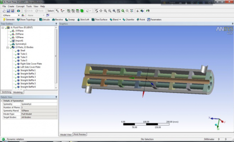
5.1 Modelling
Modelling is a pre-processor tool; the modelling of shell and tube heat exchanger is created using the CATIA software tools which is a feature-based, parametric solid modelling system with many extended design and manufacturing applications. It is sophisticated computerized software which gives friendly experience.
Figure 3. Isometric view of shell and tube type heat exchanger with straight baffle
Figure 4. Isometric view of shell and tube type heat exchanger with helical baffle
Helical baffles inside the shell and tube heat exchangers are designed in CATIA software tools shown in Figure 5.
Figure 5. Helical baffles in shell and tube heat exchangers
analytical views of straight baffle of heat exchanger are done by ANSYS software tools shown in Figure 6
Figure 6. Sectional view of straight baffle heat exchanger
Figure 7. Sectional view of helical baffle heat exchanger
This paper is explained as to show that, how the helical baffle heat exchanger has better performance than the straight baffle. For getting better efficiency, helical baffle is drawn in shell and tube type Heat Exchanger and the half sectional view is shown in Figure 7.
A. Shell Side: The Table 3 shows the results of Overall heat transfer coefficient, Pressure drop at various helix angles of Helical Baffles including Straight Baffle.
Table 3. Shell side result
|
Helix Angle (deg) |
Heat transfer Coefficient, hs W/m²k |
Over All Heat Transfer Coefficient W/m²k |
Pressure Drop Δps(Kpa) |
|
Straight |
6789.786 |
368.514 |
3.9545 |
|
10 |
19938.1529 |
382.196 |
0.3795 |
|
16 |
15259.0253 |
379.963 |
0.1634 |
|
22 |
12638.72 |
378.012 |
0.0994 |
|
28 |
10866.616 |
376.17 |
0.0629 |
B. Tube Side: The Table below shows the results of heat transfer coefficient for various input velocities of hot fluid at Tube side.
Table 4. Tube side result
|
Sl. no. |
Velocity m/sec |
Heat Transfer coefficient W/m²k |
|
1. |
1 |
6647.66 |
|
2. |
1.2 |
7670.38 |
|
3. |
1.4 |
8653.76 |
|
4. |
1.6 |
9676.48 |
|
5. |
1.8 |
10620.53 |
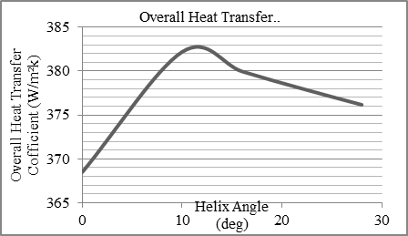
A. Overall heat transfer coefficient: Figure 8 shows the increase of overall heat transfer with the increase of helix angle and maximum value when the angle is reached at about 120 and then reduced monotonically.
Figure 8. Helix angle vs. overall heat transfer coefficient
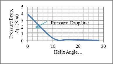
B. Pressure drop: The variation of pressure drop with helix angle is presented in Figure 9. This shows a clear idea that the pressure requires to pump in straight baffle is high when compared with Helical baffle. The pressure gradually decreases with the increase in helix angle.
Figure 9. Helix angle vs. pressure drop
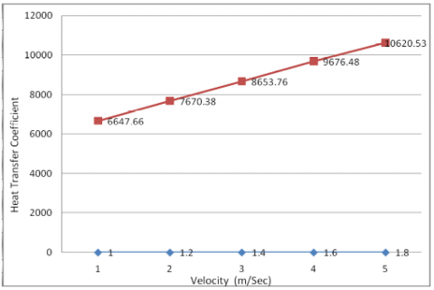
C. Heat Transfer Coefficient (Tube Side): The Heat Transfer Coefficient increases with the increase in velocity in the Tube side is shown in Figure 10.
Figure 10. Velocity vs. heat transfer coefficient (tube side)
1. The results shows the clear idea that the helical baffle heat exchanger has better overall heat transfer coefficient than the straight baffle Heat Exchanger.
2. In shell side the pressure drops are lower than the conventional straight baffle heat exchanger. The pressure drop is decreases with the increases of helix angle in all the cases considered. However, the effects of helix angles on pressure drop are small when helix angle greater than 12 degrees.
3. In Tube Side Heat Transfer Coefficient increases with the increase in Inlet Velocity. Results in greater Heat transfer.
4. Suitable helix angle may be selected based upon the desired output and industrial applications. Helix angle of 10° may provide better heat transfer than the one with an angle of 16°, however at the expense of leaser pressure drop.
5. Manufacturing cost can be increasing primarily but it can save the heat energy, remaining other constant due to that running cost should be reduced.
[1] Mukharji R. (1988). Effective design of shell and tube heat exchanger, American Institute of Chemical Engineering, Vol. 3, No. 11, pp. 17200-17204. DOI: 10.15680/IJIRSET.2014.0311016
[2] Serna M., Jimenez A. (2005). A compact formulation of the Bell Delaware method for Heat Exchanger design and optimization, Chemical Engineering Research and Design, Vol. 83, No. A5, pp. 539-550. DOI: 10.1205/cherd.03192
[3] Lei G.Y., He Y.L., Li R. Gao Y.F. (2008). Effects of baffle inclination angle on flow and heat transfer of a heat exchanger with helical baffles, Science Direct-Chemical Engineering and Processing, pp. 1-10. DOI: 10.1016/j.ijheatmasstransfer
[4] Lutcha J., Nemcansky J. (1990). Performance improvement of tubular heat exchangers by helical baffles, Chemical Engineering Research and Design, Vol. 68, pp. 263- 270. DOI: 10.1155/2011/839468
[5] Kumar P., Kumar V., Nain S. (2014). Experimental study on heat enhancement of helix changer with grooved tubes, IJLTET, Vol. 3, No. 4.
[6] Shinde S., Pancha M.H. (2012). Comparative thermal performance analysis of segmental baffle heat exchanger with continuous helical baffle heat exchanger using kern method, IJERA, Vol. 2, No. 4, pp. 2264-2271.