OPEN ACCESS
A numerical investigation on LHTESS with PCM is accomplished. The PCM used is paraffin wax. To enhance the heat transfer inside the system a highly conductive material like metal foam and ceramic nanoparticles are used. The latter method of enhancement leads to a new class of material called Nano-PCM. The system under investigation is a typical 70 L water tank filled up with pure PCM or Nano-PCM and a certain number of pipes are located where the Heat Transfer Fluid (HTF) flows. The surfaces of the pipes are assumed at a constant temperature above the melting temperature of the PCM to simulate the heat transfer from the HTF. The enthalpy-porosity theory is employed to simulate the phase change of the PCM while the metal foam is modelled as a porous media that obeys to the Darcy-Forchheimer law. The ceramics nanoparticles are modelled with the single-phase model. The simulations are accomplished for charging-discharging process at different porosities of the metal foam and different concentration of the nanoparticles. The results show that the presence of the metal foam improves the heat transfer in the system respect to the addition of the nanoparticles, reducing the melting time more than one order of magnitude.
Phase change material, LHTESS, Thermal storage, Nano-PCM, Metal foam.
The environmental problem nowadays represents new challenges for the researchers. In particular, today there is not a device capable to store indefinably the energy in thermal form. For this reason it necessary to build a buffer system that allows to charge or discharge itself in base of the evolution of demand. A Thermal Energy Storage systems (TESS) [1-2] is a device that permits to storage energy by heating a storage medium. There are two types of TESS, sensible TESS and latent TESS. In this work the Latent Thermal Energy Storage System is implemented because it has more advantages like the storing of heat maintaining the temperature nearly constant. In fact, the base material of a Latent TESS is the Phase Change Material (PCM) that during the solid-liquid phase change process, adsorbs and then releases the heat loads [3]. As reported in literature [4], PCMs have been widely suggested for thermal storage applications due to their capability of storing and releasing large amounts of energy with a small PCM volume and a relatively low temperature variation. Many applications are suitable for the PCMs, for example, an numerical study is made in [5] where the PCM is used for storage unit in thermal solar plant applications. The results showed the connection between the plant parameters with the design variables of the thermal storage device. Moreover, a study on the parameters of a PCM storage system even for thermal management applications is made in [6], where a hybrid systems with finned surfaces partially filled with PCM was studied. The results showed that t a Thermal Control Unit based on PCM is convenient for high heat loads acting in short times. Many materials can be used as PCM, but the paraffin waxes present many desirable characteristics, such as high latent heat, low vapor pressure in the melt, non-toxicity and chemical stability. However, they also have a very low thermal conductivity and therefore, different enhancement are necessary to improve the thermal conductivity of the paraffin wax for example by adding nanoparticles [7] to a base PCM or using metal foam [8]. The use of open-cell metal foam improves the effective thermal conductivity of the whole system, but reduces the effective volume of the PCM. The injection of highly conductive nanoparticles in the PCM can further enhance the rate of melting [9]. The new material created with nanoparticles in the base PCM is called Nano-PCM. About Nano-PCM, in the literature there are few researches, for example Shin and Banerjee [10], demonstrated that the nanoparticles enhances the heat capacity of the molten salt PCM. Chieruzzi et al. [11] experimentally investigate a PCM with nanoparticles and they concluded that the addition increases the latent heat of nearly 12%. Zhichao et al. [12] experimentally studied an organic PCM with TIO2 nanoparticles to enhance the thermal performance of the base PCM. The authors found that the addition of the nanoparticles by 0.2% increase the specific heat capacity. Siahpush et al. [13] studied both experimentally and numerically a thermal energy storage system using PCM and metal foam assuming the Local Thermal Equilibrium model to assess the heat transfer between PCM and metal foam. A numerical investigation on paraffin RT58 as PCM in metal foam is made in [14] using the local thermal non equilibrium model. A LTESS for concentrating solar power applications is numerically studied in [15] using the enthalpy-porosity method both charging and discharging process of the system for different geometrical configuration and metal foams.
Experimentally Zhao et al. [8] studied the phase change of the RT58 paraffin in a copper foam in order to evaluate the solid-liquid evolution of the material and the enhancement of heat transfer because of the metal foam. Furthermore a numerical model is accomplished using the local thermal equilibrium model in order to compare the experimental results with the numerical ones. Few researchers studied the Nano-PCM in metal foam, for example Hossain et al. [16] numerically studied a Cyclohexane as PCM with copper oxide nanoparticles inside a metal foam. The local thermal equilibrium is assumed the Darcy law is considered without the Forchheimer extension. The authors demonstrated that the Nano-PCM melts at a faster rate inside the porous medium. This paper numerically studied the effect of the nanoparticles and metal foam inside a pure PCM. Two different nano-PCMs are studied by adding 1% and 5% of Al2O3 inside a paraffin waxes with a melting temperature of 58°C (RT58). The thermophysical properties are calculated with the single-phase model. Two types of metal foam are evaluated for different value of porosity (80% and 90%). A typical 70L water tank TESS, filled up with PCM or nano-PCM with and without metal foam, is numerically implemented and the comparisons are made in term of charging and discharging phase and the total amount of energy. The results showed that the metal foam gives major benefits in term of rate of melting respect to the nanoparticles.
A TES is numerically implemented in 3D space as a typical 70 L water tank, filled up with pure paraffin wax or Nano-PCM with 1% or 5% of Al2O3 nanoparticles and a certain number of pipes pass through the system in order to transport the Heat Transfer Fluid. The dimensions of the TES are 120 x 157 x 710 mm but for thermal symmetry the computational domain is only a part of the whole system as showed in Fig 1.
Figure 1. Frontal view af the physical domain
An assigned temperature at 343.15 K on the pipe surface is imposed in order to simulate the heat transfer between the Heat Transfer Fluid and the system during the charging operation while during the discharging phase the temperature is imposed to 300K. A convective heat transfer on the top surface is considered while the other surfaces are adiabatic. The gravitational acceleration is along the z-axis and the Boussinesq approximation is considered in order to take into account the buoyancy force due to natural convection.
The phase change of paraffin wax is modelled with the enthalpy-porosity method [17], because it melts in a temperature range. During the phase change a mixed solid-liquid zone is developing that is described by a parameter called liquid fraction. This parameter varies from 0 to 1 in the mixed zone:
\(\left\{ \begin{align} & \beta =0\quad \quad \quad \quad \quad \quad \quad \quad for\quad T<{{T}_{SOLIDUS}} \\ & \beta =\frac{T-{{T}_{SOLIDUS}}}{{{T}_{LIQUIDUS}}-{{T}_{SOLIDUS}}}\ \ for\quad {{T}_{SOLIDUS}}<T<{{T}_{LIQUIDUS}} \\ & \beta =1\quad \quad \quad \quad \quad \quad \quad \quad for\quad T>{{T}_{LIQUIDUS}} \\ \end{align} \right.\) (1)
T is the local temperature of the cell, Tliquidus is the temperature upper which the domain is entirely liquid and Tsolidus is the temperature below which it is fully solid. The mixed zone is developed in a range of temperature between Tliquidus and Tsolidus.
The metal foam is modelled with a Darcy-Forchheimer law because it behaves like a porous media; therefore a source term is used in the momentum equation to simulate its presence. To assess the heat transfer between PCM and metal foam, the Local Thermal Equilibrium (LTE) assumption is chosen, where there is not difference of temperature between the PCM and the porous media.
A single-phase approach is assumed to model the interaction between the nanoparticles and the PCM in the liquid phase. This approach considers the Nano-PCM as a homogeneous fluid. The volume fraction of the Nano-PCM is indicates with the Greek letter β and it is the ratio between the volume of the nanoparticles and the total volume of the domain:
$\psi=\frac{V o l_{A l_{2} O_{3}}}{V o l_{T O T A L}}$(2)
The continuity equation is:
$\nabla \cdot(\rho \vec{V})=0$(3)
where $\vec{V}$ is the velocity vector of the PCM or nano-PCM in the liquid phase. The Nano-PCM is considered as a homogeneous material, so the difference of velocity between the nanoparticles and pure PCM is neglected. The same consideration is made with other physical characteristics. To simulate the natural convection in the PCM a Boussinesq approximation is used, so the density of PCM varies with temperature:
$\rho=\rho_{0}\left[1-\gamma\left(T-T_{0}\right)\right]$(4)
where ρ and T are respectively the density and the temperature of the PCM, ρ0 and T0 are the operating density and temperature and γ is the thermal expansion coefficient. The operating temperature T0 is equal to 321 K. The momentum equation is [15]:
$\rho\left(\frac{\partial \vec{V}}{\partial t}+(\nabla \cdot \vec{V}) \vec{V}\right)=\mu_{P C M}\left(\nabla^{2} \vec{V}\right)-\overrightarrow{\nabla p}+\vec{S}$(5)
where t is the time, μPCM is the viscosity of the PCM or Nano-PCM; p is the relative pressure and $\vec{S}$ is a source term vector that includes all of following terms [15]:
$\vec{S}=\rho \vec{g} \gamma\left(T-T_{0}\right)+\left(\frac{(1-\beta)^{2}}{\left(\beta^{3}+0.001\right)^{3}} A_{m u s h}+\frac{\mu}{K}+\frac{C_{F}}{\sqrt{K}} \rho|\vec{V}|\right) \vec{V}$(6)
The first term models the natural convection in the liquid phase of the material according to the Boussinesq approximation. The second term models the presence of the solid part in the mixed region, where the small number (0.001) avoids the division by zero [15] when β is null. Amush is the mushy zone constant which represents the damping of the velocity to zero during the solidification [18]. Its value does not influence the value of melting time. In these simulations the value of mushy zone constant is set to 105 Kg/s. The third term is the Darcy term where K is the permeability of the porous media and the last term is the Forchheimer term, where CF is inertial drag factor. The permeability and drag factor values are calculated with the following relations, by Calmidi et al. [19]:
$K=0.00073(1-\varepsilon)^{-0.24}\left(\frac{d_{f}}{d_{p}}\right)^{-1.11} d_{p}^{2}$ (7)
$C_{F}=0.00212(1-\varepsilon)^{-0.132}\left(\frac{d_{f}}{d_{p}}\right)^{-1.63}$(8)
The equation of energy for PCM in the metal foam is [20]:
$\overline{\rho c} \frac{D T}{D t}=k_{e f f} \nabla^{2} T-\varepsilon \rho_{P C M} H_{L} \frac{\partial \beta}{\partial t}$(9)
The product $\overline{\rho c}$ is evaluated as the weighted average of the densities of metal foam and PCM [20]:
$\overline{\rho c}=(1-\varepsilon) \rho_{m} c_{m}+\dot{o} \rho_{P C M} c_{P C M}$(10)
where ρm and cm are respectively the density and specific heat of the metal foam, ε is the porosity of the metal foam and cpcm is the specific heat of PCM or nano-PCM. keff is the effective thermal conductivity calculated by [20]:
$k_{e f f}=(1-\varepsilon) k_{m}+\varepsilon k_{P C M}$(11)
km e kpcm are respectively the thermal conductivities of metal foam and PCM. HL is the latent heat of the PCM. To calculate the values of the proprieties of the nano-pcm, the following relations [21] are used:
$\rho_{N A N O P C M}=(1-\psi) \rho_{P C M}+\psi \rho_{P A R T C L E S}$(12)
$\left(\rho c_{P}\right)_{N A N O P C M}=(1-\psi)\left(\rho c_{P}\right)_{P C M}+\psi\left(\rho c_{P}\right)_{P A R T I C L E S}$(13)
$(\rho \gamma)_{N A N O P C M}=(1-\psi)(\rho \gamma)_{P C M}$(14)
where the subscript NANOPCM indicates the physical characteristic of the nano-pcm, the subscript PCM indicates the physical characteristic of pure paraffin wax, the subscript PARTICLES indicates the physical characteristic of the material of the nanoparticles (aluminum oxide). $\psi$ is the volume fraction of the nano-PCM, cP is the specific heat and γ is the thermal expansion factor. The viscosity is calculated by [22]:
$\mu_{NANOPCM}=\frac{\mu_{PCM}}{(1-\psi)^{2.5}}$(15)
and the thermal conductivity is calculated from the Maxwell equation [23]:
${{k}_{NANOPCM}}={{k}_{PCM}}\frac{{{k}_{PARTICLES}}+2{{k}_{PCM}}-2\psi ({{k}_{PCM}}-{{k}_{PARTICLES}})}{{{k}_{PARTICLES}}+2{{k}_{PCM}}+\psi ({{k}_{PCM}}-{{k}_{PARTICLES}})}$ (16)
where μNANOPCM is the viscosity of the nano-pcm. The values are not change a lot at varying of the volume fraction. The latent heat of the nano-pcm is evaluated using [7]:
$\left(H_{L}\right)_{N A V O P C M}=\frac{(1-\psi)^{*}\left(\rho H_{L}\right)_{P C M}}{\rho_{N A N O P C M}}$(17)
The melting temperature is the same for all of three types of material. The pure PCM is the paraffin RT58 purchased from Rubitherm technologies GmbH [22]. The nanoparticles are made of oxide aluminum (Al2O3). The nano-PCMs considered have a volume fraction equal to 1% and 4%. The metal foam is made of aluminum [18]. The numerical simulations are made with the commercial code ANSYS Fluent [25] using the finite volume approach. For the mesh independence solution three different meshes were tested with different nodes 27630 nodes, 51322 nodes, 104556 nodes and the mesh with 27630 nodes was chosen because it represents the best compromise between the computational costs and accuracy. A comparison with the work of Krishnan et al. [26] was accomplished for the validation of the model.
Table 1. Thermal properties of the materials
|
|
RT 58 |
Al2O3 |
Al. |
Nanopcm 1% |
Nanopcm 5% |
|
Density [Kg/m3] |
840 |
3980 |
2719 |
871.4 |
965.6 |
|
Specific Heat[J/kg K] |
2100 |
850 |
871 |
2042.9 |
1893.9 |
|
Thermal Conductivity [W/m K] |
0.2 |
35 |
202.4 |
0.206 |
0.2245 |
|
Dynamic Viscosity [Kg/ ms] |
0.0269 |
- |
- |
0.0276 |
0.0298 |
|
Thermal expansion factor [1/K] |
1.1e-4 |
- |
- |
1.05e-4 |
9.19e-5 |
|
Latent Heat [J/Kg] |
180000 |
- |
- |
171779 |
150323 |
|
Tsolidus[K] |
321 |
- |
- |
321 |
335 |
|
Tliquidus [K] |
335 |
- |
- |
321 |
335 |
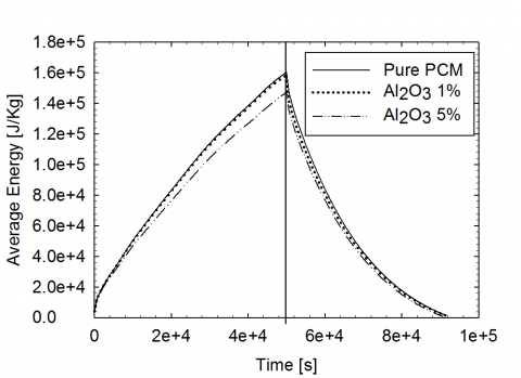
The results are evaluated in terms of average liquid fraction, temperature and energy storage during the time, for the pure paraffin wax, the Nano-PCM at 1% and 5% of Al2O3 and Nano-PCM with metal foam both for charging phase and discharging phase. In figure 2 there is a comparison between three cases of PCM and nano-PCM without metal foam for different nanoparticles concentrations. It can be seen that the liquid fraction (figure 2a) tends to rise faster when the concentration of nanoparticles increase even that the path is same during the time. This behavior can be explained by the growing of the value of thermal conductivity at the increasing of the concentration of nanoparticles into PCM.
(a)
(b)
Figure 2. Average Liquid Fraction and energy as function of time for Pure PCM and Nano-PCM with 1% and 5% of Al2O3 in charging and discharging phases
Nevertheless the discharging phase is similar between the pure PCM and nano-PCM. It can be noted that the discharging phase is faster than the charging phase because of the heat loss on the top surface of the domain. The evolution of the energy stored shows that the addition of the nanoparticles leads to a worsening of the energy stored.
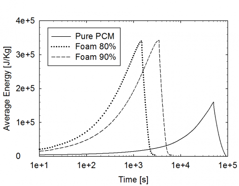
In figure 3 there is a comparison between the pure PCM and PCM with metal foam for different values of porosity, 80% and 90%. It is possible to see that the presence of the metal foam significantly improve the charging and discharging phase more than one order of magnitude. Moreover the metal foam with 80% of porosity increase the evolution of the charging and discharging processes respect to the porosity of 90%. This behavior can be explain as a consequence of equation (10) of the effective thermal conductivity, where at lower porosity the effective thermal conductivity of the system is higher. Nevertheless the energy stored is inferior for lower porosities because the volume of the PCM in the system is lesser.
(a)
(b)
Figure 3. Average Liquid Fraction and energy as function of time for Pure PCM and PCM with metal foam at 80% and 90% of porosity in charging and discharging phases
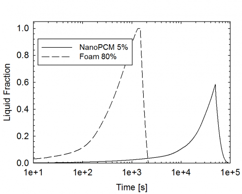
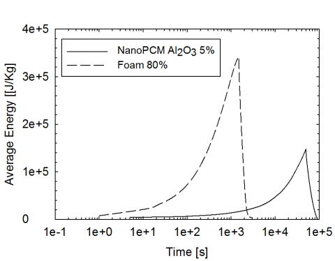
In figure 4 is depicted the average liquid fraction and energy stored as function of time for Nano-PCM at 5% of Al2O3 and the pure PCM with metal foam at 80% of porosity.
(a)
(b)
Figure 4. Average Liquid Fraction and energy as function of time for Nano-PCM at 5% of Al2O3 and PCM with metal foam at 80% of porosity in charging and discharging phases
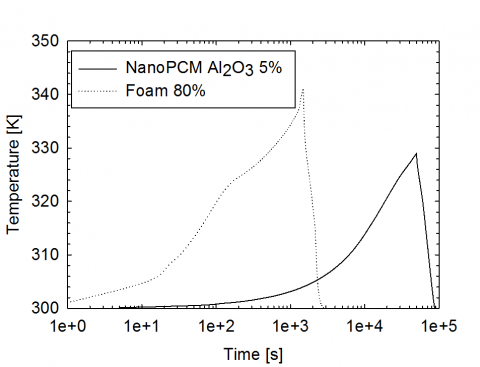
The metal foam improves significantly the heat transfer and then the rate of melting respect to the nano-PCM. Moreover, the energy stored is higher for the metal foam, because it has a thermal conductivity larger than the nano-PCM, and therefore the temperature inside the system is higher, leading to more energy stored during the charging process, as it showed in figure 5.
Figure 5. Evolution of the average temperature as function of time for Nano-PCM at 5% of Al2O3 and PCM with metal foam at 80% of porosity for charging and discharging phase
This paper is focused on a numerical study concerning the use of the nano-PCMs and metal foam for thermal storage application. The RT58 paraffin wax was chosen and two type of improvements were built, the nano-PCM with oxide alumina (Al2O3) at 5% and the pure PCM with metal aluminum foam for two types of porosity. Generally, the presence of metal foam improves significantly the thermal performance of the system instead of the nanoparticles. For this reason the metal foam can be used to increase greatly the rate of charging or discharging process while the nanoparticles can be used to adjust only moderately the storing and releasing thermal processes in order to obtain a preferable value of the charge and discharge time.
|
Amush |
Mushy constant, Kg. s-1 |
|
c |
Specific heat, J. kg-1. K-1 |
|
Cf |
Inertial drag factor |
|
d |
Diameter, m |
|
g |
gravitational acceleration, m.s-2 |
|
HL |
Latent Heat of PCM, J. kg-1 |
|
k |
Thermal conductivity, W.m-1. K-1 |
|
K |
Permeability, m2 |
|
p |
Relative Pressure, Pa |
|
S,\(\overrightarrow{s}\) |
Source term |
|
t |
Time, s |
|
T |
local temperature, K |
|
V,\(\overset{\to }{\mathop{V}}\,\) |
Velocity of liquid PCM, m.s-1 |
|
Vol |
Volume [m3] |
|
Greek symbols |
|
|
β |
Liquid Fraction |
|
γ |
Thermal expansion coefficient, K-1 |
|
ψ |
volume Fraction |
|
ε |
porosity |
|
µ |
dynamic viscosity, kg. m-1.s-1 |
|
ρ |
Density, kg. m-3 |
|
Subscripts |
|
|
0 |
Reference quantity |
|
Al2O3 |
Oxide aluminum |
|
eff |
effective |
|
f |
Foam fiber |
|
Liquidus |
Liquidus |
|
m |
Metal foam |
|
NANOPCM |
nanopcm |
|
p |
Foam pore |
|
PARTICLES |
Nanoparticles of Al2O3 |
|
PCM |
Phase change material |
|
Solidus |
Solidus |
|
TOTAL |
Total quantity |
[1] A. Gil, M. Medrano, I. Martorell, A. Lázaro, P. Dolado, B. Zalba and L. F. Cabeza, “State of the art on high temperature thermal energy storage for power generation. Part 1 – Concepts, materials and modellization,” Ren. Sust. En. Re., vol. 14, no. 1, pp. 31-55, Jan. 2010. DOI: 10.1016/j.rser.2009.07.035.
[2] A. Gil, M. Medrano, I. Martorell, A. Lázaro, P. Dolado, B. Zalba and L. F. Cabeza, “State of the art on high temperature thermal energy storage for power generation. Part 2 – Case Studies,” Ren. Sust. En. Re., vol. 14, no. 1, pp. 56-72, Jan. 2010. DOI: 10.1016/j.rser.2009.07.036.
[3] Mancin, S., Diani, A., Doretti, L., Hooman, K. and Rossetto, L., “Experimental analysis of phase change phenomenon of paraffin waxes embedded in copper foams,” Int. J. Therm. Sci., vol. 90, pp. 79-89, April 2015. DOI: 10.1016/j.ijthermalsci.2014.11.023.
[4] Zalba, B., Marìn, J. M., Cabeza, L. F. and Mehling, H., “Review on thermal energy storage with phase change: materials, heat transfer analysis and applications,” Appl. Therm. Eng., vol. 23, no. 3, pp. 251-283, Feb. 2003. DOI: 10.1016/S1359-4311(02)00192-8.
[5] G. Cammarata, L. Monaco, L. Cammarata and G. Petrone, “A Numerical Procedure for PCM Thermal Storage Design in Solar Plants”, Int. J. Heat Tech., vol. 31, no. 2, pp. 105-110, 2014, DOI: 10.18280/ijht.3102.14.
[6] G. Casano and S. Piva, “Parametric Analysis of a PCM Energy Storage System”, Int. J. Heat Tech., vol. 33, no. 4, pp. 61-68, 2015, DOI: 10.18280/ijht.330408.
[7] Khodadadi J.M., Hosseinizadeh S.F., “Nanoparticle-enhanced phase change materials (NEPCM) with great potential for improved thermal energy storage,” Int. Commun. Heat Mass Transfer, vol. 34, no. 5, pp. 534–543, May 2007. DOI: 10.1016/j.icheatmasstransfer.2007.02.005.
[8] Zhao C.Y., Lu W. and Tian, Y., “Heat transfer enhancement for thermal energy storage using metal foams embedded within phase change materials (PCMs),” Sol. En., vol. 84, no. 8, pp. 1402-1412, Aug. 2010. DOI: 10.1016/j.solener.2010.04.022.
[9] Yang Y. Y., Luo L., Song G. L., Liu Y. and Tang G., “The experimental exploration of nano-Si3N4/paraffin on thermal behavior of phase change materials,” Thermochim. Act.,vol. 597, pp. 101-106, Dec. 2014. DOI: 10.1016/j.tca.2014.10.014.
[10] D. Shin and D. Banerjee, “Enhanced Specific Heat of Silica Nanofluid,” J. H. Transf., vol. 133, no. 024501. DOI: 10.1115/1.4002600.
[11] M. Chieruzzi , G. F. Cerritelli, A. Miliozzi and J. M. Kenny, “Effect of nanoparticles on heat capacity of nanofluids based on molten salts as PCM for thermal energy storage,” Nanoscale Res. Lett., vol. 8, no. 1, pp. 448, Oct. 2013. DOI: 10.1186/1556-276X-8-448.
[12] L. Zhichao, Z. Qiang and W. Gaohui, “Preparation and enhanced heat capacity of nano-titania doped erythritol as phase change material,” Int. J. Heat Mass Transfer, vol. 80, pp. 653–659, Jan 2015. DOI: 10.1016/j.ijheatmasstransfer.2014.09.069.
[13] A. Siahpush, J. O’Brien and J. Crepeau, “Phase change heat transfer enhancement using copper porous foam,” ASME J. of H. Tran., vol. 130, no. 082301, May 2008. DOI: 10.1115/1.2928010.
[14] Y. Tian and C. Y. Zhao, “A numerical investigation of heat transfer in phase change materials (PCMs) embedded in porous metals,” Energy, vol. 36, no. 9, pp. 5539-5546, Sep 2011. DOI: 10.1016/j.energy.2011.07.019.
[15] K. Nithyanandam and R. Pitchumani, “Computational studies on metal foam and heat pipe enhanced latent thermal energy storage,” J. H. Trans., vol. 136, no. 051503, Feb 2014. DOI: 10.1115/1.4026040.
[16] R. Hossain, S. Mahmud, A. Dutta and I. Pop, “Energy storage system based on nanoparticle-enhanced phase change material inside porous medium,” Int. J. Therm. Sci., vol. 91, pp. 49-58, May 2015. DOI: 10.1016/j.ijthermalsci.2014.12.023.
[17] V. R. Voller and C. Prakash, “A fixed grid numerical modelling methodology for convection-diffusion mushy region phase-change problems,” Int. J. Heat Mass Trans., vol. 30, no. 8, pp.1709-1719, Aug. 1987. DOI: 10.1016/0017-9310(87)90317-6.
[18] A. Al-abidi, S. Bin Mat, K. Sopian, M. Y. Sulaiman and A. Th. Mohammed, “CFD application for latent heat thermal energy storage: a review,” Ren. Sust. En. Re., vol. 20, pp. 353-363, Apr. 2013. DOI: 10.1016/j.rser.2012.11.079.
[19] V. V. Calmidi and R. L. Mahajan, “Forced Convection in High Porosity Metal Foams,” ASME J. Heat Transfer, vol. 122, no. 3, pp. 557-565, Feb. 2014. DOI: 10.1115/1.1287793.
[20] Z. Liu, Y. Yao and H. Wu, “Numerical modeling for solid–liquid phase change phenomena in porous media: Shell-and-tube type latent heat thermal energy storage,” Appl. En., vol. 112, pp.1222–1232, Dec. 2013. DOI: 10.1016/j.apenergy.2013.02.022.
[21] S. S. Sebti, M. Mastiani, H. Mirzaei, A. Dadvand, S. Kashani and S. A. Hosseini, “Numerical study of melting of nano-enhanced phase change material in a square cavity,” Alex. Eng. J., vol. 14, no. 5, pp. 307-316, Dec. 2015. DOI: 10.1016/j.aej.2015.09.007.
[22] H. C. Brinkman, “A calculation of the viscous force exerted by a flowing fluid on a dense swarm of particles,” Appl. Scie. Res., vol 1, pp.27-34, Dec. 1949. DOI: 10.1007/BF02120313
[23] J. C. Maxwell, “Treatise on electricity and Magnetism,” Clarendon, Oxford, 1879.
[24] Rubitherm GmBH, www.rubitherm.de.
[25] Ansys Incorporated, Fluent 15.0 User Manual, 2014.
[26] S. Krishnan, J. Y. Murthy and S. V. Garimella, “A two-temperature model for solid–liquid phase change in metal foams,” ASME J. Heat Transfer, vol. 127, pp. 995–1004, Nov. 2004. DOI: 10.1115/1.2010494.