OPEN ACCESS
In the paper a 3D numerical solution of two real shell-and-tube heat exchangers, with different type of baffles, segmental and pseudo-helical, is presented, through the use of commercial codes, in order to evaluate the influence of the baffles type on heat exchanger performance. The parameters to be evaluated, which influence the efficiency of the thermal exchange and the maintenance and pumping costs, are the pressure drops, the heat transfer coefficient and the fouling resistance. The fluid dynamic study of the shell-and-tube heat exchanger is conducted under stationary flow conditions. In the paper, furthermore, the results of the thermohydraulic analysis, performed under stationary flow conditions, more “helical baffles” exchangers, with different baffles helix angle, are presented. Exchangers with pseudo-helical baffles inclined by 7°, 20°, 30° and 40° are analyzed. The simulations are carried out considering a real fluid, approximately incompressible, under laminar flow conditions. Finally, to verify the correctness of the results, they are compared with correlations in the literature.
Heat exchanger, Segmental baffles, Helical baffles, Thermo-hydraulic analysis.
The well-established tendency to improve and optimize the recovery of heat, during the design of new equipment, involves constant research for innovative technical solutions, which ensure higher performance with less heat exchange surface area [1, 2]. Also, there can be situations where there is a certain limitation on providing more heat exchanger surface area, particularly in the case of revamping of existing equipment, where the pumping capacity and the overall dimensions could be already fixed [3].
This design trend requires heat exchangers which use as little of the process stream momentum as possible in flow-through equipment. Precisely to vary the velocity and turbulence on the shell side and therefore the heat transfer coefficient, baffles can be used, in order to induce the fuid on the shell side to travel a tortuous path. The baffles have, in addition, an important task from the mechanical point of view; they support, in fact, the tubes of the bundle, keeping them equally spaced, and preventing the vibrations of the tubes themselves. On the shell side, the conventional segmental baffle exhibits significant pressure differences to produce a sufficiently high heat transfer rate, low efficiency zones, mixed flow, bypass or recirculated currents. Therefore new types of baffles, such as helical baffles, have been proposed.
A shell-and-tube heat exchanger with pseudo-helical baffles, commonly called “helical baffles” heat exchanger, is a viable alternative to the traditional heat exchanger with segmental baffles. It succeeds, in fact, in reconciling an increase in equipment performance with a relatively simple production and installation technology. This type of baffle is represented by circular sector plates positioned sequentially, with both horizontal and vertical angle, in order to impart a helical path to the fluid, on the shell side. “Helical baffles” heat exchangers are generally used in oil and gas plants and refineries in the petrochemical and chemical industries [4, 5].
In the work, a 3D numerical simulation of a real heat exchanger was performed, considering first the type with segmental baffles and, later, the one with pseudo-helical baffles, through the use of commercial codes, in order to compare the performance of the two types taken into consideration. Moreover, the performance of “helical baffles” heat exchanger with different baffles helix angle were studied.
CFD simulations results, finally, were compared with those obtained by the application of some correlations available in the literature [6].
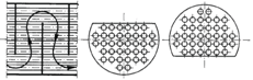
Shell-and-tube heat exchangers consist of expanded or welded tubes on two tube plates, placed inside the shell. In general, the baffles are placed inside the shell, which is of the perforated plates that have the dual aim of supporting the tubes and of making the external fluid to the tubes (the shell side) pass a more tortuous route. In this way, they improve the velocity, increase the turbulence, and consequently, the heat transfer coefficient. As already mentioned, the baffles have, in addition, an important task from the mechanical point of view; they support, in fact, the tubes of the bundle, keeping them equally spaced, and preventing the vibrations of the same. The conventional segmental baffle (Figure 1) exhibits rather high pressure differences to produce a sufficiently high heat transfer rate, dead zones, mixed flow, bypass or recirculated currents (Figure 2). Therefore new types of baffles, such as helical baffles, have been proposed.
Helical baffles are pseudo-circular shaped plates mounted inside the coat sequentially, in order that the shell side flow follows a helical path. Each baffle occupies one quadrant of the cross-section and has a certain inclination with the centerline of the exchanger. Four baffles make one set baffle and the fluid returns to its starting situation after crossing the set. Helical baffles consist of two major types [7]:
Figure 1. Single-segment baffles
Figure 2. Flow pattern for the segmental baffles arrangement [3]
A correct arrangement of pseudo-helical baffles in shell and tube heat exchangers seems to provide two advantages. First, since the shell side flow pattern is similar to the plug flow condition, there will be significant improvements of the temperature due to the reduction of back mixing; second, an occurrence of the shear velocity profile generated by the vortex core creating a vortex which favorably and markedly affects the film heat transfer coefficient.
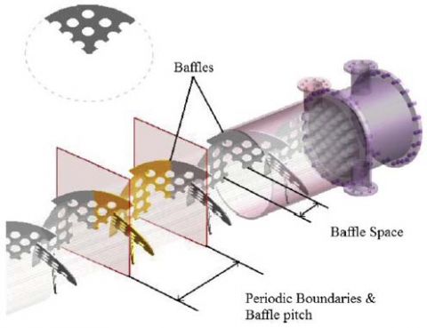
Figure 3. Positions of periodic boundary, baffle pitch and baffle space [8]
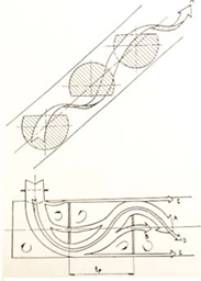
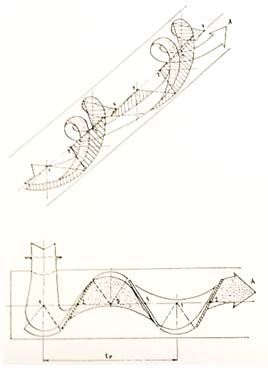
Figure 4 shows the flow pattern for pseudo-helical baffles.
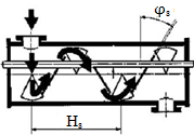
In designing shell and tube heat exchangers with pseudo-helical baffles, pitch angle, baffle arrangement, and the space between two baffles with the same position are important parameters. Baffles pitch angle js is the angle between flow and perpendicular surface on exchanger axis and Hsis space between two following baffles with the same situation (Figure 5).
Figure 4. Flow pattern for pseudo-helical baffles [3]
Figure 5. A schematic of heat exchangers with pseudo-helical baffles [9]
The fluid dynamic study of the shell-and-tube heat exchangers is conducted, in most cases, under conditions of stationary flow and, also in the case of heat exchangers with non-continuous helical baffles, the same analysis can be performed.
In the paper a thermohydraulic analysis was carried out, performed under stationary flow conditions, with more “helical baffles” exchangers and with different baffles helix angle (7°, 20°, 30°and 40°).
The geometric parameters of the analyzed exchangers are given in Table 1.
Table 1. Geometric parameters of the analyzed exchangers
|
Element |
Size and description |
|
Shell side parameters |
|
|
Di [mm] |
200 |
|
Material |
SA 516 Gr.70 |
|
Tube parameters |
|
|
de [mm] |
19 |
|
Length [mm] |
1,092 |
|
Number |
37 |
|
Pitch [mm] |
25.4 |
|
Material |
SA 213 T5 |
|
Baffle parameters |
|
|
Thickness [mm] |
3 |
It is appropriate that the type of shell-and-tube heat exchanger with segmental baffles should provide for a baffle space of not less than 1/5 of the internal diameter of the shell, according to design practice, as shown in Figure 6. Segmental baffles of the “cut 25 %” type were considered for the thermal-hydraulic analysis.
Figure 6. Segmental baffles with pitch greater than 1/5Di
By virtue of the length of the tubes used, the analyzed exchangers are made up of 7 segmental baffles and of 72, 24, 12, 12 pseudo-helical baffles, respectively, for a pitch angle of 7°, 20°, 30°and 40°.
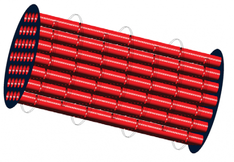
In Figure 7 and in Figure 8, the geometries, created by a commercial code, for an exchanger with segmental baffles and for exchangers with pseudo-helical baffles, are shown.
The fluid considered that circulates on the shell side is Crude Oil, whose thermophysical properties are shown in Table 2.
A fluid flow rate of 50 kg/s was used.
Figure 7. Heat exchanger with segmental baffles
Figure 8. Heat exchanger with pseudo-helical baffles
Table 2. Thermophysical properties of Crude Oil
|
Properties |
T = 82 °C |
T = 135 °C |
|
Density ρ [kg.m-3] |
917 |
887 |
|
Specific heat cp [J.kg-1.K-1] |
2,050 |
2,260 |
|
Thermal conductivity k [W.m-1.K-1] |
0.098 |
0.092 |
|
Viscosity μ [kg.m-1.s-1] |
0.0393 |
0.00693 |
The simulations, carried out using the 3D double precision FLUENT code, were carried out considering a real fluid, approximately incompressible, under laminar flow conditions. The system, owing to the complex geometry, presents the areas that would be involved in recirculation, especially in proximity to the baffles. Considering what has been said, it is natural to use the pressure-based solver, which determines the velocity field from the field of pressure with the verification on the pressure control equation (continuity equation). In the calculation, the resolution of the energy equation is activated, since it is a heat transfer problem.
The operating pressure, in the case of incompressible flow, does not assume a significant role, therefore, is not used by software in the calculation of the density since this is considered constant.
To make a fair comparison the same boundary conditions were laid, for all simulations: mass flow inlet for inlet section, outflow for outlet section, wall for baffles and tube bundle.
SIMPLE algorithm [10] is used and under-relaxation factors set were the following: pressure 0.3, density 1, body 1, momentum 0.7, energy 0.1.
The algorithm for the resolution of the pressure is Standard. The discretization of the momentum and energy equations is occurred using a UpWind scheme of first order.
The simulations were performed on grids defined mesh independent, or with a grid with an error less than 5 %, with respect to a grid with fewer elements. The error between two different grids is determined by root mean squared error (RMSE), defined by Eq.(1):
$R M S E=\sqrt{\frac{1}{N} \cdot \sum_{i=1}^{N}\left(x_{i}-\hat{x}_{i}\right)^{2}}$(1)
where xirepresent the engineering magnitude of interest; in the present case, being also interested in the calculation of the pressure drops, the pressure is the magnitude of which the mesh independence will be performed. RMSE has the same unit of measure of the magnitude engineering taken as a reference, for which, so that it can be calculated the percentage error, useful to have immediately an order of magnitude for the quantification of the error, it is essential with a normalization respect to reference value. The application of this implies that the vectors to be compared are of equal size. Since the grids of the different number of elements it has become essential to the execution of an interpolation points using the functions of Matlab.
3.1 Grids generation
Grids generation was carried out by the commercial code GAMBIT. On each grid the mesh independence was verified, and on each mesh independent the quality control was carried out. Particular importance of quality control of the mesh have Aspect Ratio, which quantifies the deviation of an element from the equilateral shape, and Equiangle Skew, which gives a measure of the distortion of the element [11, 12, 13].
In Table 3, depending on the type of heat exchanger analyzed, the cells number constituting the grids for the mesh independence is reported. The following notation is used: S to indicate the heat exchangers with segmental baffles and P.E to indicate the heat exchangers with pseudo-helical baffles.
In Table 4, depending on the type of heat exchanger analyzed, the values of Aspect Ratio, Equiangle Skew and RMSE are shown. For the obtained results, the grids can be defined as good quality.
Table 3. Cells number constituting the grids for the mesh independence
|
Typology |
Cells |
|
S |
2,356,000 |
|
P. E φs = 7° |
2,431,400 |
|
P. E φs = 20° |
958,984 |
|
P. E φs = 30° |
1,959,980 |
|
P. E φs = 40° |
2,345,000 |
|
Typology |
Aspect Ratio |
Equiangle Skew |
RMSE |
|
S |
< 4 |
< 0.85 |
2.10 % |
|
P. E φs = 7° |
< 20 |
< 0.85 |
3.00 % |
|
P. E φs = 20° |
< 4 |
< 0.85 |
4.50 % |
|
P. E φs = 30° |
< 4 |
< 0.85 |
2.50 % |
|
P. E φs = 40° |
< 4 |
< 0.85 |
2.35 % |
The fundamental parameters to be determined are the film heat transfer coefficient and the pressure drop of the heat exchanger analyzed. For a greater deepening of the fluid dynamic aspect, an analysis of the shell side velocity profiles was also carried out, to have an additional index of comparison.
3.2.1 Film heat transfer coefficient
The film heat transfer coefficient h shell side is of fundamental importance for thermo-hydraulic analysis of shell-and-tube heat exchanger since it is the quality index of the exchange itself. The code FLUENT allows its evaluation through a surface integrals on area-weighted average; the values obtained for the heat exchangers analyzed are shown in Table 5.
Table 5. Heat transfer coefficient for the different studied exchangers
|
Typology |
h [W.m-2.K-1] |
|
Heat exchanger with segmental baffles |
150.19 |
|
Heat exchanger with pseudo-helical baffles φs = 7° |
156.09 |
|
Heat exchanger with pseudo-helical baffles φs = 20° |
157.14 |
|
Heat exchanger with pseudo-helical baffles φs = 30° |
162.79 |
|
Heat exchanger with pseudo-helical baffles φs = 40° |
163.87 |
From Table 5 it can be observed that there is an increase of the film heat transfer coefficient changing from a heat exchanger with segmental baffles to one with pseudo-helical baffles. These increases, in percentage terms, compared to the values obtained from a heat exchanger with segmental baffles, are presented in Table 6.
Table 6. Increases of coefficient h at variation of the baffles helix angle
|
φs |
Increase |
|
S |
- |
|
7° |
3.93 % |
|
20° |
4.63 % |
|
30° |
8.39 % |
|
40° |
9.11 % |
The heat exchanger type “helical baffles”, compared to the type with segmental baffles, presents greater heat exchange efficiency with an increase ranging between 4 and 9 %. Moreover, with reference to Table 5, it is observed that the values of the film heat transfer coefficient increases with the angle of inclination of the baffles. Table 7 shows in percentage terms, increases in coefficient h obtained from the comparison of different configurations with the one having a helix angle of 7 degrees.
For a complete analysis, the optimal angle of inclination for pseudo-helical baffles was estimated. Simulating a shell-and-tube “helical baffles” heat exchanger with helix angle of 45°, according to the previously defined geometric parameters, it denotes a reduction of 19 % of the film heat transfer coefficient h compared to the type with helix angle of 40°. Therefore, increasing the angle of inclination of the “helical baffles” increases the film heat transfer coefficient; this effect, however, for a helix angle greater than 40° is no longer valid.
Table 7. Increases of the coefficient h to vary the baffles helix angle
|
φs |
Increase |
|
7° |
- |
|
20° |
0.67 % |
|
30° |
4.29 % |
|
40° |
4.98 % |
3.2.2 Pressure drops
The estimate of pressure drops is of fundamental importance, since they have a strong incidence on the plant pumping costs. The shell side pressure drops are created just by the arrangement of the baffles.
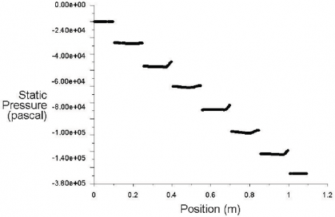
Figure 9 shows the trend of the pressures to a heat exchanger with segmental baffles. A discontinuity of the pressure due to the presence of the baffle itself can be seen. The pressure drops between input and output (DP = Ping − Pout) of heat exchanger have been quantified in 347 kPa.
Figure 9. Pressure trend in the heat exchanger with segmental baffles
Figures 10, 11, 12, and 13 show the trends of the pressure for the heat exchangers with pseudo-helical baffles at variation of the angle of inclination of the baffles themselves. Also in this case, there is a discontinuity of the pressure due to the presence of the baffles. The pressure drops between input and output, at variation of the angle of inclination, are reported in Table 8.
Figure 10. Pressure trend in the “helical baffles” heat exchanger, φs = 7°
Figure 11. Pressure trend in the “helical baffles” heat exchanger, φs = 20°
Figure 12. Pressure trend in the “helical baffles” heat exchanger, φs = 30°
Figure 13. Pressure trend in the “helical baffles” heat exchanger, φs = 40°
Table 8. Pressure drops in “helical baffles” heat exchanger, at variation of the helix angle φs
|
φs |
DP [kPa] |
|
7° |
126.43 |
|
20° |
14.41 |
|
30° |
5.40 |
|
40° |
4.32 |
Figure 14. Fluid path through shell side
The fluid, in “helical baffles” heat exchangers, follows a helical path, much softer than that in a zigzag configuration, characteristic of the traditional heat exchangers. Consequently to this, in the latter, there are considerable recirculation phenomena involving a separation and a mixing of the fluid after the passage of the baffle. A more uniform path of the fluid also results in a less sedimentation of the solid particles and, hence, in less fouling in the heat exchanger [14].
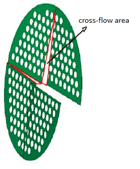
Table 8 shows, moreover, that the pressure drops of a shell-and-tube “helical baffles” heat exchanger with helix angle of 7° are more than two orders of magnitude greater compared to that with a helix angle of 20°. This is due to the increase of the passage area (Figure 15) caused by the increase of the angle of inclination of the “helical baffles” that creates a more uniform path to the fluid.
Figure 15. Passage area [15]
3.2.3 Velocity along the direction of flow
The trend of the fluid velocity along the direction of flow is very important for a more precise fluid dynamic analysis.
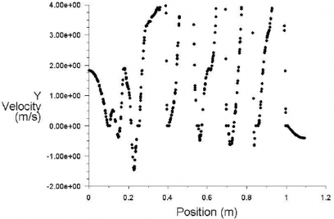
In Figure 16, the velocity trend of a heat exchanger with segmental baffles is shown, while, Figures 17, 18, 19 and 20, show the same trend for the heat exchangers with pseudo-helical baffles with different helix angles.
Figure 16. Velocity trend in the heat exchanger with segmental baffles
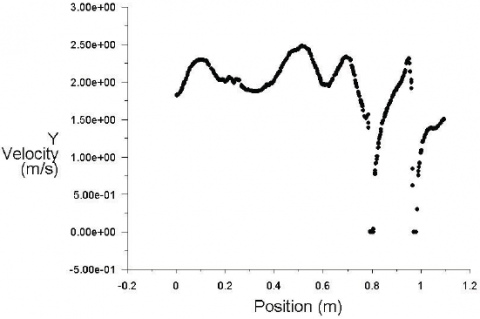
Figure 17. Velocity trend in the “helical baffles” heat exchanger, φs = 7°
Figure 18. Velocity trend in the “helical baffles” heat exchanger, φs = 20°
Figure 19. Velocity trend in the “helical baffles” heat exchanger, φs = 30°
Figure 20. Velocity trend in a “helical baffles” heat exchanger, φs = 40°
With reference to Figures 16-20, it is observed that, for the “helical baffles” type, the velocity trend along the flow direction is less fluctuating compared to the trend that occurs in a heat exchanger with segmental baffles. This brings benefits, in terms of vibrations, inside the heat exchanger. This effect becomes more and more noticeable as the angle of inclination of the baffles increases. This is due to the decrease of the numbers of baffles and the increase of passage area (Figure 15). A more uniform and homogeneous distribution of the velocity results in less formation of fouling and, consequently, fewer erosions and corrosions inside the shell.
Furthermore, in the vicinity of the baffles, there is a noticeable recirculation phenomena which decreases with increasing the angle of inclination.
The results obtained from a CFD analysis of the heat exchangers with pseudo-helical baffles were compared with those obtained from empirical correlations available in the literature. In particular, the Stehlik et al. correlations [6] were taken into account for a comparison of the heat transfer coefficient (Table 9, Figure 21) and on the pressure drops (Table 10, Figure 22).
In the same tables are also given the differences between the two solutions obtained.
Table 9. Comparison between coefficient h obtained by CFD analysis and Stehlik et al. correlation
|
φs |
h [W.m-2.K-1] CFD analysis |
h [W.m-2.K-1] Stehlik correlation |
Difference [%] |
|
7° |
156.09 |
151.29 |
3.17 |
|
20° |
157.14 |
152.41 |
3.10 |
|
30° |
162.79 |
156.98 |
3.70 |
|
40° |
163.87 |
158.68 |
3.27 |
Figure 21. Comparison of coefficient h obtained by CFD analysis to the Stehlik et al. correlation
Table 10. Comparison of DP values obtained by CFD analysis to the Stehlik et al. correlation
|
φs |
DP [kPa] CFD analysis |
DP [kPa] Stehlik correlation |
Difference [%] |
|
7° |
126.43 |
115.6 |
9.37 |
|
20° |
14.41 |
13.5 |
6.74 |
|
30° |
5.4 |
5.1 |
5.88 |
|
40° |
4.32 |
4.15 |
4.10 |
Figure 22. Comparison of DP values obtained by CFD analysis to the Stehlik et al. correlation
In the paper a 3D numerical solution of two real shell-and-tube heat exchangers, with different type of baffles, segmental and pseudo-helical, has been presented, through the use of commercial codes, in order to compare the performance of the two types taken into consideration.
The thermal-hydraulic analysis, performed under stationary flow conditions, was conducted for several “helical baffles” exchangers, with different baffles helix angle. Exchangers with pseudo-helical baffles inclined by 7°, 20°, 30° and 40° were analyzed. The simulations were carried out considering a real fluid, approximately incompressible, under laminar flow conditions.
CFD analysis denotes that the use of a “helical baffles” heat exchanger, compared to a traditional exchanger (with segmental baffles), involves:
These effects are much more evident at greater inclination of the angle of the baffle. It is not recommended, however, to have angles of inclination greater than 40°, since for higher angles there would be a decrease of the heat transfer coefficient h. The use of a “helical baffles” heat exchanger with inclination angle less than 7° is not recommended either, since the pressure drops would be too high. The optimum baffles helix angle is 40°, although marked benefits are already obtained at an angle of 30°.
Finally, for the exchangers with different angle of inclination, a comparison of the film heat transfer coefficient and the pressure drops, with the correlations of Stehlik et al. [6] was carried out. These correlations, compared to the results provided by the CFD analysis, present a deviation variable from 3.10 % to 3.70 % on the film heat transfer coefficient, and variable between 4.10 % and 9.37 % on pressure drops.
|
cP |
specific heat, J. kg-1. K-1 |
|
Di de |
internal diameter of the shell, mm external diameter of the tubes, mm |
|
Hs h k N Ping Pout RMSE xi $\hat{\mathbf{x}}_{i}$ |
space between baffles with the same situation, mm film heat transfer coefficient, W. m-2. K-1 fluid thermal conductivity, W. m-1. K-1 elements number of the mesh pressure in the inlet section, kPa pressure in the output section, kPa root mean squared error engineering magnitude of interest, kPa engineering magnitude of reference, kPa |
|
Greek symbols |
|
|
ΔP |
pressure drops, kPa |
|
µ |
dynamic viscosity, kg. m-1.s-1 |
|
$\varphi_{s}$ |
angle of inclination of the baffles, grad. |
|
ρ |
fluid density, kg. m-3 |
[1] K. Sivakumar and K. Rajan, “ Experimental analysis of heat transfer enhancement in a circular tube with different twist ratio of twisted tape inserts,” International Journal of Heat and Technology, vol. 33, no. 3, pp. 158-162, 2015. DOI: 10.18280/ijht.330324.
[2] D. Kaliakatsos, M. Cucumo, V. Ferraro, M. Mele, A. Galloro and F. Accorinti, “CFD analysis of a pipe equipped with twisted tape,” International Journal of Heat and Technology, vol. 34, no. 2, pp. 172-180, 2016. DOI: 10.18280/ijht.340203.
[3] J. Lutcha and J. Nemcansky, “Performance improvement of tubular heat exchangers by helical baffles,” Chemical Engineering Research and Design, vol. 68, no. 3, pp. 263-270, 1990.
[4] Y. G. Lei, Y. L. He, R. Li and Y. F. Gao, “Effects of baffle inclination angle on flow and heat transfer of a heat exchanger with helical baffles,” Chemical Engineering and Processing, vol. 47, no. 12, pp. 2336-2345, 2008. DOI: 10.1016/j.cep.2008.01.012.
[5] V. G. Chekmenev, E. V. Karmanov, V. G. Lebedev, G. V. Golubinskii and V. N. Zamidra, “Shell-and-Tube heat exchangers with a helical baffle”, Chemistry and Technology of Fuels and Oils, vol. 40, no. 1, pp. 39-43, 2004.
[6] P. Stehlik, J. Nemcansky, D. Kral and L. W. Swanson, “Comparison of correction factors for shell-and-tube heat exchangers with segmental or helical baffles,” Heat Transfer Engineering, vol. 15, no. 1, pp. 55-65, 1994. DOI: 10.1080/01457639408939818.
[7] J. F. Zhang, Y. L. He and W. Q. Tao, “3D numerical simulation on shell-and-tube heat exchangers with middle-overlapped helical baffles and continuous baffles - Part II: Simulation results of periodic model and comparison between continuous and noncontinuous helical baffles,” International Journal of Heat and Mass Transfer, vol. 52, no. 23, pp. 5381-5389, 2009. DOI: 10.1016/j.ijheatmasstransfer.2009.07.007.
[8] F. N. Taher, S. Z. Movassag, K. Razmi and R. T. Azar, “Baffle space impact on the performance of helical baffle shell and tube heat exchangers,” Applied Thermal Engineering, vol. 44, pp. 143-149, 2012. DOI: 10.1016/j.applthermaleng.2012.03.042.
[9] M.R. Jafari Nasr and A. Shafeghat, “Fluid flow analysis and extension of rapid design algorithm for helical baffle heat exchangers,” Applied Thermal Engineering, vol. 28, no. 11, pp. 1324-1332, 2008. DOI: 10.1016/j.applthermaleng.2007.10.021.
[10] R. Pletcher, J. Tannehill and D. Anderson, Computational Fluid Mechanics and Heat Transfer, II ed.; Philadelphia, USA: Taylor & Francis, 1997.
[11] J. D. Anderson, Computational Fluid Dynamics-The Basics with Applications. USA: McGraw-Hill, 1995.
[12] J. Blazek, Computational Fluid Dynamics: Principles and Applications, Elsevier, 2001.
[13] F. M. White, Viscous Fluid Flow, II ed., USA: McGraw-Hill, 1991.
[14] D. Q. Kern and R. E. Seaton, “A Theoretical Analysis of Thermal Surface Fouling,” Br. Chem. Eng., vol. 4, no. 5, pp. 258-269, 1959.
[15] S. K. Shinde and P. V. Hadgekar, “Numerical comparison on Shell side performance of Helixchanger with center tube with different helix angles,” International Journal of Scientific and Research Publications, vol. 3, no. 8, 2013.