OPEN ACCESS
The objective of this numerical study is to investigate the best geometric configuration that maximises heat transfer from the heated base by allowing both the length of the solid substrate and the microchannel heat sink freedom to morph. The thermal performance of the microchannel is based on the minimised peak temperature on the heated surface which gives a global minimised thermal resistance. The optimisation of the geometric parameters of the heat sink and solid substrate is carried out using a computational fluid dynamics code with a goal-driven optimisation algorithm. Results of the effect of Bejan number on the minimised peak temperature and minimised thermal resistance for solid substrate with varying axial lengths of 1 to 10 mm but fixed volume of 0.9 mm3 is presented. Results of optimal channel aspect ratio, solid volume fraction and channel hydraulic diameter of the microchannel were also presented.
Forced Convection, Minimised Peak Temperature, Minimised Thermal Resistance; Microchannel, Aspect Ratio.
The constructal law which is the evolutionary principle of increase of flow access in time [1, 2] has been used by many researchers to determine best geometric configuration of heat sinks that maximise heat transfer from heated surfaces or volumes to the cooling fluid.
Muzychka [3] carried out an analytical study using constructal design approach to determine the optimal passage size to length ratio in terms of Bejan number for different shapes of cooling channels that maximises heat transfer rate per unit volume. A simple optimal duct shape was developed in his study. In another investigation carried out by Muzychka [4], a constructal multi-scale design approach was presented which allowed for maximum heat dissipation in systems using circular micro-tubes. Results obtained from his study showed that the use of multi-scale design techniques gives greater performance of heat sink core structures when compared with conventional design approaches.
Bello-Ochende et al. [5] also used the constructal approach to determine numerically the best possible geometry for a microchannel heat sink with fixed axial length and volume which minimises peak temperature when the pressure difference across the volume is fixed. Their results showed that optimal microchannel shape and minimised peak temperature were functions of the applied pressure difference and solid volume fraction.
Some other studies that were carried out to investigate fluid flow and heat transfer in microchannel heat sinks using constructal approach were by Bello-Ochende et al. [6–8], Adewumi et al. [9], Olakoyejo et al. [10], Salimpour et al. [11] and Xie et al. [12] to mention a few.
In the search for the optimal configuration of the microchannel carried out in these studies outlined above, both the volume and axial length of the solid were both fixed except for the investigation carried out by Bello-Ochende et al. [6] where results of optimised microchannel geometry were presented for relaxed axial length. In their study, the variation of the surface heat flux q″ on the heated wall with changes in axial length was not considered because they assumed a constant surface heat flux of 100 W/cm2.
Microelectronic chips release heat load Q on the surface of the solid substrate on which they are mounted and the surface area of this solid substrate is used to calculate the surface heat flux q″. This means that if the axial length and width of the solid substrate is free to morph, the surface heat flux q″ will vary. This variation in surface heat flux is taken into consideration in this present study. The objective of this study is to search for the optimal geometric configuration of both the solid substrate and microchannel heat sink that minimises the peak temperature on the heated surface when the total volume is fixed but axial length is varied. This numerical investigation is carried out using a computational fluid dynamics code with a goal-driven optimisation tool.
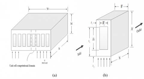
In real applications, many microchannels are arranged in a solid substrate for effective cooling of the substrate. However, after applying symmetry conditions on the physical model shown in Figure 1a, an elemental volume is taken as the computational model as shown in Figure 1b. Using an elemental volume as the computational model is the constructal approach because we are starting from a basic construction unit [5].
Figure 1. Single microchannel heat sinks (a) Physical model (b) Computational volume
The length N, height M and width W of the solid was allowed to morph while the total volume of microchannel V was fixed. The geometric dimensions t1, t2, t3, t5, Hc and Wc were also allowed to vary but subject to manufacturing constraints shown in Equations (4-6). The solid volume fraction or porosity $\phi$ is defined as the ratio of the solid volume to the total volume of the heat sink, which is only dependent on the cross-sectional area of the heat sink as shown in Equation (9).
$\phi=\frac{V_{\text { solid }}}{V}=\frac{A_{\text {solid}} N}{A N}=\frac{A_{\text {solid}}}{A}=\frac{M W-H_{c} W_{c}}{M W}$(1)
The fixed global volume is defined as
$V=M W N=$const(2)
The aspect ratio AR of the solid substrate is $\frac{M}{W}$
The hydraulic diameter Dh is defined as
$\frac{2 H_{c}}{\left(A R_{c}+1\right)}$(3)
Where ARc is the channel aspect ratio defined as $\frac{H_{c}}{W_{c}}$
The manufacturing constraints [6] are
$\frac{H_{c}}{W_{c}} \leq 20$(4)
$t_{2} \geq 50 \mu m$(5)
$M-t_{3} \geq 50 \mu m$(6)
The total heat load on the heated bottom wall Q is 100 W where Q is defined as
$Q=n q^{\prime \prime} N W$(7)
where NW is the elemental surface area that is heated and the number of microchannels n is assumed to be 100.
2.1 Basic equations and boundary conditions
The present study assumes that the flow is steady and laminar. The cooling fluid, which is water, is also assumed to be incompressible and homogeneous with temperature-dependent thermophysical properties. The thermophysical properties of water were defined using the piecewise-linear function of temperature as shown in Equation (8) below [13]. Radiation and natural convection are assumed to be negligible.
$\eta(T)=\eta_{a}+\frac{\eta_{a+1}-\eta_{a}}{T_{a+1}-T_{a}}\left(T-T_{a}\right)$(8)
Where 1 ≤ a ≤ L and L is the number of segments while $\eta$ is the fluid property.
The temperature distribution within the geometry used in this study was determined by solving the conservation of mass, momentum and energy Equations (9)-(12) numerically. The governing equations solved after applying the above assumptions are,
$\nabla \cdot \vec{v}=0$(9)
$\rho(\vec{v} \cdot \nabla \vec{v})=-\nabla P+\mu \nabla^{2} \vec{v}$(10)
$\rho_{f} C_{p f}(\vec{v} \cdot \nabla T)=k_{f} \nabla^{2} T$(11)
The energy equation for the solid regions can be written as:
$k_{s} \nabla^{2} T=0$(12)
The heat flux between the interface of the fluid and the solid walls is coupled and its continuity between the interface of the solid and the liquid is given as:
$\left.k_{s} \frac{\partial T}{\partial n}\right|_{w a l l}=\left.k_{f} \frac{\partial T}{\partial n}\right|_{w a l l}$(13)
The inlet boundary conditions p = Pin , v = w =0, T = Tin where $P_{m}=\frac{B e \alpha \mu}{V^{\frac{2}{3}}}+P_{o u t}$. Be known as Bejan number [14, 15] is the dimensionless pressure difference and $\alpha=\frac{k}{\rho C_{p}}$. At the outlet, the boundary condition is specified as, Pout = Patm. Symmetry boundary conditions are specified at the left and right side of the domain. A no-slip boundary condition is specified at the walls. The measure of performance is the global thermal resistance which is expressed as
$R_{t h}=\frac{\Delta T}{Q}$(14)
where the peak wall temperature difference ΔT is
$\Delta T=T_{\max }-T_{\min }$(15)
The Navier-Stokes mass conservation and energy Equations (9-12) along with the specified boundary conditions were solved numerically using a three-dimensional computational fluid dynamic code [13], which employs a finite volume method. The detail of this method is explained by Patankar [16]. The computational domain was meshed using hexagonal/wedge, tetrahedron and pyramid elements. The momentum and energy equations were solved using the second-order upwind scheme and the coupling of the pressure and velocity fields were controlled using the SIMPLE algorithm. The solution is assumed to converge when the normalised residuals of the continuity and momentum equation fall below 10-5 while that of the energy equation falls below 10-7. The convergence criterion for the peak temperature as the quantity monitored is,
$\gamma=\left|\frac{(\Delta T)_{i}-(\Delta T)_{i-1}}{(\Delta T)_{i}}\right| \leq 0.01$(16)
where i is the mesh iteration index. The mesh is more refined as i increases and i-1 mesh was selected as the convergence criterion when Equation (16) was satisfied. The mesh refinement tests and code validation was already carried out in our previous study [9].
The computational fluid dynamics code used in this study [13] has a goal-driven optimisation (GDO) tool which is used to carry out the geometric optimisation of the microchannel heat sinks. It uses the response surface methodology (RSM) for its optimisation process. The RSM uses a group of mathematical and statistical techniques to develop an adequate functional relationship between a response of interest and a number of input variables, which has been thoroughly explained in literature [17, 18]. When the response surface methodology is applied to computer simulation experiments, it is used to build a model of the system being investigated. This model is called a metamodel. It is on this metamodel that optimisation is carried out.
Numerical simulations and optimisation were carried out for a fixed total volume V of 0.9 mm3 with varied axial length N of 1 to10 mm. The temperature of water pumped across the micro-channel was 20 ˚C at the inlet and total heat load applied to the bottom wall was 100W. The design space for the response surface for the fixed total volume was defined as 50 ≤ Wc ≤ 80 µm, 50 ≤ M - t3 ≤ 60 µm, and 500 ˂ Hc ˂ 3000 µm. The optimised design point chosen was required to meet the manufacturing constraints for pressure drops of 10 to 60kPa which corresponds to the range of Bejan number 6.5 x 10⁷ ≤ Be ≤ 3.9 x 10⁸.
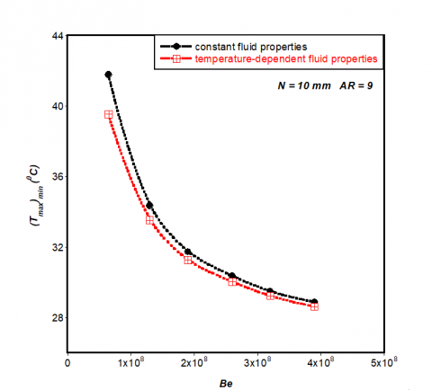
In our previous study [9], the thermophysical properties of water, which is the cooling fluid, were assumed constant. In this present study, temperature-dependent property of water was considered and results of minimised peak temperature were compared to those of the previous study.
Figure 2 showed that at the lowest Be used in this study, the result of minimised peak temperature when constant fluid properties assumptions was made was 5% more than when temperature-dependent properties of fluid was used for the numerical simulation. This variation reduces as the Be is increased and for the Be of 3.9 x 10⁸, the difference between the two results was less than 1%. It can be concluded from the result shown in Figure 2 that it is not accurate to assume constant fluid properties for water at low pressure drops.
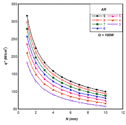
Figure 3 showed how varying the axial length of the solid substrate affects the surface heat flux q″ on the heated wall for the constant heat load Q of 100W and fixed total volume of 0.9 mm3. It was observed that as the length is increased from 1 to 10 mm, q″ reduces. The results also showed decreasing surface heat flux as the solid substrate aspect ratio was decreased for all the axial lengths investigated.
Figure 2. Effect of dimensionless pressure drop on minimised peak temperature
Figure 3. Effect of varying axial length on surface heat flux
The effect of varying the axial length of the solid substrate on the minimised peak temperature is shown in Figure 4. The results showed that at fixed AR of 3, the optimal axial length Nopt was 3 mm when Be = 6.5 x 10⁷, but as Be increased, Noptwas discovered to be 5 mm. Increasing the axial length above 5 mm did not further improve the thermal performance of the microchannel rather the minimised peak temperature increased.
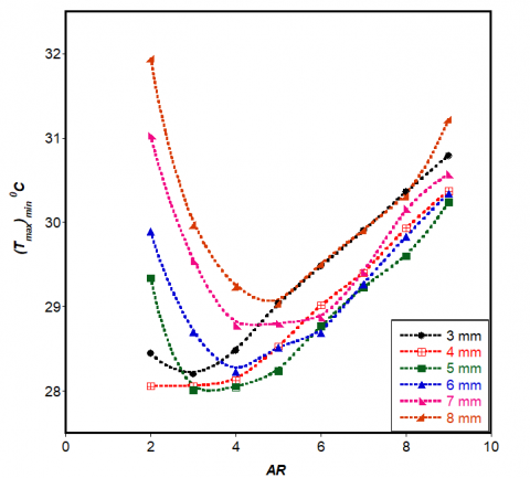
Figure 5 shows results of the effect of varying AR on the minimised peak temperature at a fixed Bejan number Be = 1.3 x 10⁸. It was observed that the optimal AR =3 for axial length ≤ 5 mm but became ˃ 3 as N increased. Results in Figure 4 and 5 showed that global ARoptthat minimises the peak temperature was 3.
Figure 4. Effect of varying axial length on minimised peak temperature for AR = 3
Figure 5. Effect of varying solid substrate aspect ratio AR on minimised peak temperature for Be = 1.3 x 10⁸
The results of global optimal channel aspect ratio, solid volume fraction, channel hydraulic diameter, solid substrate aspect ratio and axial length are shown in Figure 6. For the lowest Be,$\left(A R_{c}\right)_{o p t} \approx 11 \phi_{o p t} \approx 0.8$ and $N_{o p t}=3 \mathrm{mm}$ but when Be was 1.3 x 10⁸ to 3.9 x 10⁸, the optimal channel aspect ratio and solid volume fraction were $\approx$8 and 0.7 respectively while$N_{o p t}=5 m m$. The optimal channel hydraulic diameter $\left(D_{h}\right)_{o p t} \approx 140 \mu m$ and the solid substrate aspect ratio $(A R)_{o p t}=3$for all Be considered in this study.
Figure 6. Optimal microchannel and solid substrate dimensions
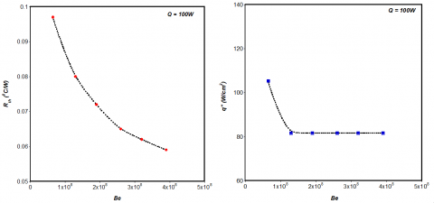
The results of global thermal resistance and corresponding surface heat flux for the optimal microchannel and solid substrate dimensions are shown in Figure 7. As the Be decreases Rth decreases from 0.097 to 0.059 ˚C/W while the
surface heat flux q″ was discovered to decrease from 105.41W/cm2 when Be = 6.5 x 10⁷ to a constant value of 81.65W/cm2 as the Be increased from 1.3 x 10⁸ to 3.9 x 10⁸.
Figure 7. Effect of dimensionless pressure drop on the (a) global minimised thermal resistance (b) surface heat flux
In this paper it has been shown by numerical investigations that the global thermal resistance of a microchannel heat sink with varying axial length can be minimised by optimising the geometric dimensions of both the microchannel and the solid substrate while taking into consideration changes in the surface heat flux. For a fixed total volume V of 0.9 mm3 and constant heat load Q of 100W on the heated wall, the optimal axial length was discovered to be 3 mm with minimised peak temperature of 29.68˚C, minimised global thermal resistance of 0.097˚C/W and surface heat flux of 105.41W/cm2 at pressure drop of 10kPa which corresponds to Be = 6.5 x 10⁷.
As the Be was increased, the optimal axial length increased and became fixed at 5 mm. The global optimal solid substrate aspect ratio AR was a fixed value of 3 for the range of Be considered in this study. Results of optimal channel aspect ratio, solid volume fraction and channel hydraulic diameter were also presented in this paper.
The funding obtained from NRF, TESP, University of Stellenbosch/ University of Pretoria, SANERI/SANEDI, CSIR, EEDSM Hub and NAC is acknowledged and duly appreciated.
1. Bejan, A., Lorente, S., “The constructal law and the thermodynamics of flow systems with configuration,” Int. J. Heat Mass Transf, 47 (14), 3203–3214, 2004. DOI: 10.1016/j.ijheatmasstransfer.2004.02.007.
2. Bejan, A., Lorente, S., “The constructal law and the evolution of design in nature,” Phys. Life Rev., 8 (3), 209–240, 2011. DOI: 10.1016/j.plrev.2011.05.010.
3. Muzychka, Y.S., “Constructal design of forced convection cooled microchannel heat sinks and heat exchangers,” Int. J. Heat Mass Transf., 48 (15), 3119–3127, 2005. DOI: 10.1016/j.ijheatmasstransfer.2005.02.014.
4. Muzychka, Y.S., “Constructal multi-scale design of compact micro-tube heat sinks and heat exchangers,” Int. J. Therm. Sci., 46 (3), 245–252, 2007. DOI: 10.1016/j.ijthermalsci.2006.05.002.
5. Bello-Ochende, T., Liebenberg, L., Meyer, J.P., “Constructal cooling channels for micro-channel heat sinks,” Int. J. Heat Mass Transf., 50 (21), 4141–4150, 2007. DOI: 10.1016/j.ijheatmasstransfer.2007.02.019.
6. Bello-Ochende, T., Meyer, J.P., and Ighalo, F., “Combined numerical optimisation and constructal theory for the design of micro-channel heat sinks,” Numer. Heat Transf. Part A Appl., 58, 1–32, 2010.
7. Bello-Ochende, T., Liebenberg, L., Meyer, J.P., “Constructal design : geometric optimization of micro-channel heat sinks,” (December) 483–489, 2007.
8. Bello-Ochende, T., Liebenberg, L., Malan, A.G., Bejan, A., Meyer, J.P., “Constructal Conjugate Heat Transfer in Three-Dimensional Cooling Channels,” J. Enhanc. Heat Transf. 14 (4), 279–293, 2007. DOI: 10.1615/JEnhHeatTransf.v14.i4.20.
9. Adewumi, O.O., Bello-Ochende, T., Meyer, J.P., “Constructal design of combined microchannel and micro pin fins for electronic cooling,” Int. J. Heat Mass Transf. 66 315–323, 2013. DOI: 10.1016/j.ijheatmasstransfer.2013.07.039.
10. Olakoyejo, O.T., Bello-Ochende, T., Meyer, J.P., “Mathematical optimisation of laminar forced convection heat transfer through a vascularised solid with square channels,” Int. J. Heat Mass Transf., 55 (9), 2402–2411, 2012. DOI: 10.1016/j.ijheatmasstransfer.2011.12.036.
11. Salimpour, M.R., Sharifhasan, M., Shirani, E., “Constructal optimization of the geometry of an array of micro-channels,” Int. Commun. Heat Mass Transf., 38 (1), 93–99, 2011. DOI: 10.1016/j.icheatmasstransfer.2010.10.008.
12. Xie, G., Zhang, F., Sundén, B., Zhang, W., “Constructal design and thermal analysis of microchannel heat sinks with multistage bifurcations in single-phase liquid flow,” Appl. Therm. Eng. 62 (2), 791–802, 2014. DOI: 10.1016/j.applthermaleng.2013.10.042.
13. ANSYS FLUENT 14.0 User’s Guide, vol. 15317, 2011.
14. Petrescu, S., “Comments on the optimal spacing of parallel plates cooled by forced convection,” Int. J. Heat Mass Transf., 37, 1283, 1994. DOI: 10.1016/0017-9310(94)90213-5.
15. Bhattacharjee, S., Grosshandler, W.L., “The formation of a wall jet near a high temperature wall under microgravity environment,” ASME 1988 Natl. Heat Transf. Conf., Vol. 1, 1 711–716, 1988.
16. Pantakar, S.V., Numerical Heat Transfer and Fluid Flow, Hemisphere Publishing Corp., New York, USA 1980.
17. Khuri, A.I., Mukhopadhyay, S., “Response surface methodology,” Wiley Interdiscip. Rev. Comput. Stat., 2 (2), 128–149, 2010.
18. Myers, R.H., Montgomery, D.C., Anderson-Cook, C.M., Response Surface Methodology: Process and Product Optimization Using Designed Experiments, John Wiley & Sons, 2009.