OPEN ACCESS
Using computational analysis, convective heat transfer enhancement and entropy generation of laminar flows through wavy channels was examined. A three-dimensional geometry was used for simulation. The simulation was performed using non dimensional governing equations for a steady laminar flow. The flow is both thermally and hydrodynamically developing while the channel walls are kept at a constant temperature. The computations were conducted with Reynolds number ranging from 100 to 2000 using water (Pr = 7.0) as the working fluid. The numerical simulation was carried out by using two different diameter ratio (W = L/D) and three different wave ratio (Y = P/D) to reach the optimal geometry with the maximum performance evaluation criterion. The results showed that the heat transfer performance in wavy channel was enhanced than a typical circular channel. The pressure drop also increased in case of wavy channel and smaller wave ratio has more friction penalty. Generally, the heat transfer performance of wavy channel has an enhanced heat transfer performance because of the thermal boundary layer disturbance and block of longitudinal heat transfer.
Heat transfer, Enhancement, Laminar flow, Wavy channel, Boundary layer.
Energy efficiency and energy saving are one of the major scientists concern in the past era because of the increase in energy global demand and consumption as result of commercial growth and population growth. A temperature exchanger is a piece of equipment built for efficient heat transfer from one medium to another. The media may be disjointed by a compact wall to prevent mixing or they may be in direct contact.
They are extensively used in space heating, refrigeration, air conditioning, power plants, chemical plants, petrochemical plants, petroleum refineries, natural gas processing, and sewage treatment [1]. Depending on the path of flow occurring between the two media, heat exchangers are classified as Cross-flow, Parallel flow and Counter flow.
There are three various methods to do enhancement of convective heat transfer, namely, inserted devices, modification of ducts and integral roughness. The method of liking depends on two factors, the performance and cost. This objective can be attaining in two ways active and passive augmentation. The active augmentation is less common because it requires addition of external power (e.g., an electromagnetic field) to cause a desired flow modification. In the passive enhancement, it involves of alteration to the heat transfer surface or integration of a device whose presence effects in a flow field modification. The most popular augmentation is the vortex generator. Vortex generators are the surfaces which are used to enhance the rate of heat transfer dissipation from heated surfaces to other fluids.
Vortex generators can be positioned on plane surfaces, tubes, or other geometries. These surfaces have been used to increase heat transfer rate by adding additional surface area and encouraging mixing. When number of vortex generator are used to increase heat transfer under natural convection conditions the optimal geometry of vortex generator (corresponding to a maximum rate of heat transfer) should be used, provided this is compatible with available space and financial limitations.
The common vortex generator (twisted tape, delta wings, wavy channel, wavy tape, etc) used widely to increase the rates of convection heat transfer.
The complications of flow and heat transfer of fluid in a wavy channel have been studied numerically and experimentally by many researchers. Rush et al. [2] investigated experimentally the fluid flow and heat transfer features in sinusoidal wavy channels. Laminar forced convection in the entry region of a wavy-channel was solved numerically by Mohamed et al. [3] using the finite-volume approach. By using CLEARER algorithm a 3D fluid flow and heat transfer characteristics in triangular wavy fin-and-tube heat exchanger have been numerically studied by Cheng et al. [4]. Heris et al. [5, 6] investigated the laminar flow and heat transfer of nanofluid by addition of nanoparticles to base fluid in a circular tube and found considerable enhancement of heat transfer. Besides wavy duct vortex generator is also one of the most important member in terms of heat transfer enhancement. Vortex Generators have been intensively investigated recently [7-21]. Jacobi et al. [22-28] studied on wavy finned tube with different configurations of delta wing vortex generators.
From the literature review shows that in overall most of the research work focused on simple wave ratio. Furthermore, most of the research works used water as a working fluid. The purpose of the present work is to introduce the combined effect of the wave ratio and diameter ratios by using water as a working fluid.
The geometrical configurations of the wavy channel discussed in the present computational work are shown in Figure. 1. The length of the channel is 2000 mm which are fixed in this research and two hydraulic diameter of the wavy channel are tested as 20 mm and 25 mm. The inlet temperature boundary condition is given 300 K, whereas wall temperature set as 500 K. In this section, combined effect of the wave ratio and diameter ratios are mainly investigated, and the results are compared with that of the smooth channel. The three different wave ratios, (Y = 0.5, 1.0 and 1.5) are tested, whereas two diameter ratio (W = 80.0 and 100.0) are used in this computation..
Figure 1. Physical model of a wavy channel
In the present numerical study, three-dimensional convective heat transfer enhancement of laminar flow of water through a wavy channel is simulated.
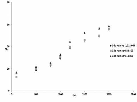
Three-dimensional numerical simulation model of wavy channel having non uniform grid was generated, in order to critically examine the flow and heat transfer. Different grid sizes were tested as part of grid independence study as shown in Figure 2. The grid generations and numerical simulations are performed using commercial Ansys 15.0 software package Gambit and Fluent respectively. The regions in the channel close to the tube wall are meshed into smaller control volumes in order to find more precise prediction results. From the Figure 2 one can see that Nusselt number is less that 4-6 % among the other grids. A mesh consisting of 933,400 cells were used for the present computation.
Figure 2. Grid independence study
The simplified form of continuity, momentum and energy equations for a 3-D, steady state, incompressible flow and laminar forced convection heat transfer without viscous dissipation are given below.
Continuity equation
$\frac{\partial u_{i}}{\partial x_{i}}=0$(1)
Momentum equation
$\rho\left(u_{i} \frac{\partial u_{j}}{\partial x_{i}}\right)=-\frac{\partial p}{\partial x_{i}}+\frac{\partial}{\partial x_{i}}\left(\left(\mu+\mu_{t u v b}\right) \frac{\partial u_{i}}{\partial x_{i}}\right)$(2)
Energy equation
$\left(u_{i} \frac{\partial \Theta}{\partial x_{i}}\right)=\frac{\partial}{\partial x_{i}}\left(\left(\alpha+\frac{v_{\text {thrb}}}{\operatorname{Pr}_{\text { turb }}}\right) \frac{\partial \Theta}{\partial x_{i}}\right)$(3)
The governing equations are discretized by using the control volume method [29]. The SIMPLE algorithm is used to confirm the combination between velocity and pressure.
(1) Considering the water flow in the channel with heat transfer, the mathematical model applied is composed of the conservation equations of mass, momentum and energy for incompressible flow in three dimensions with the following assumptions:
• The flow is three-dimensional, laminar and stationary.
• The thermo-physical properties of the water are assumed to be constant.
• The thermal conductivity of the walls and strips is assumed to be constant
Considering the water flow in the channel with heat transfer, the mathematical model applied is composed of the conservation equations of mass, momentum and energy for incompressible flow in two dimensions.
The Reynolds number of water flow in the duct is calculated from:
$R e=\frac{\rho v D_{i}}{\mu}$(6)
Steady state values of the plate and water temperatures in the duct were used to determine the values of useful parameters, namely heat supplied to the water “Qu” and heat transfer coefficient “h” calculated as:
$\mathrm{Q}_{\mathrm{u}}=\mathrm{m} \mathrm{C}_{\mathrm{p}}\left(\mathrm{T}_{\mathrm{ao}}-\mathrm{T}_{\mathrm{ai}}\right)$(7)
$h=\frac{q}{T_{\text {wall}, A v g}-T_{b}}$(8)
$N u=\frac{h D_{i}}{K}$(9)
The friction factor is determined from the measured values of pressure drop (∆P), across the test section length.
$\mathrm{f}=\frac{2 \Delta \mathrm{PD}_{\mathrm{h}}}{4 \rho \mathrm{LV}^{2}}$(10)
To evaluate the effect of heat transfer enhancement under given pumping power, the formula of performance evaluation criteria is employed by Fan et al. [30]
$\eta=\frac{\mathrm{Nu}}{\mathrm{Nu}} /\left(\frac{\mathrm{f}}{\mathrm{f}_{0}}\right)^{0.33}$(11)
where Nu and Nu0 are Nusselt numbers for the enhanced tube and the smooth tube respectively, f and f0 are friction coefficients for enhanced tube and smooth tube respectively.
Guo et al. [31] proposed a concept about the enhancement of heat transfer called as field synergy principle. Principle which states that a computed value called synergy angle between the velocity and temperature gradient can facilitate the understanding of enhanced heat transfer structures.
Average synergy angle is given by,
$\beta_{\mathrm{m}}=\cos ^{-1}\left(\frac{\int|\overrightarrow{\mathrm{U}}||\overrightarrow{\mathrm{V}} \mathrm{T}| \cos \beta \mathrm{d} \mathrm{V}}{\int|\overrightarrow{\mathrm{U}}||\overrightarrow{\mathrm{V}} \mathrm{T}| \mathrm{d} \mathrm{V}}\right)$(12)
For convection heat transfer problems the entropy generation per unit length (Sgen) was given by Bejan [32] as:
$S_{g e n}=\frac{q^{2}}{\pi \lambda \times T_{b u l k}^{2} \times N u}+\frac{m^{3} c_{f} \times 32}{\pi^{2} \times \rho^{2} \times T_{b u l k} \times D^{5}}$(13)
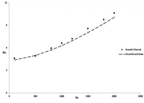
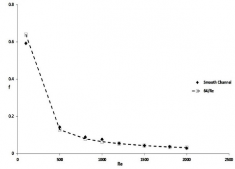
By doing computations, the result obtained for heat transfer and friction factor characteristics in the smooth channel (straight channel) are verified in terms of Nusselt number and friction factor. The predicted results from the proposed correlations are shown in Figure 3-4. According to this figures, the present results are in good agreement with the Churchill and Ozoe’s Nusselt number [33] and f = 64/Re friction factor correlations [32] with tolerances of ± 2.9 % and ± 4%, respectively.
Following formulae were used to calculate the dimensionless parameters:
Graetz number: $G Z=\frac{\pi}{4} \frac{R e \times P r}{\frac{x}{D}}$(14)
Rayleigh number: $\mathrm{Ra}=\mathrm{Gr} \times \mathrm{Pr}$(15)
Grashof number: $G r=g \beta\left(T_{w, m}-T_{f, m}\right) D^{3} / v^{2}$(16)
Correlation proposed by Churchill and Ozoe [33] for laminar flow is,
$Nu= 4.364[1+(Gz/29.6)^2]^{\frac{1}{6}}{1+[\frac{\frac{Gz}{19.04}}{[1+(Pr/0.0207)^{2/3}]^{1/2}×[1+(Gz/29.6)^2]^{1/3}}]^{3/2}}^{1/3}$(17)
$\mathrm{f}=64 / \mathrm{Re}$(18)
The rate of heat transfer of wavy channel in terms of Nu number is shown in Figure. 5. The overall results show that the increase in Nusselt number is complemented by the increase in Reynolds number. Also, one can see from the Figure 5 that wavy channel with combine effect of wavy ratio and diameter ratio have good heat transfer than the smooth channel. The small diameter ratio and wave ratio (W = 80.0, Y =0.5) showing some promising result than the other tested wavy channels. This effect can be clarified by a decrease in the flow cross-sectional area, an increase in turbulence intensity and a growth in tangential flow proven by wavy nature. Furthermore, the figure shows that in both diameter ratio (W = 100.0 and 80.0), the heat transfer increases by decreasing the wave ratio. The swirl intensity increases by decreasing the wave ratio and therefore increases the Nusselt number.
Figure 3. Validation of wavy channel model: Heat transfer as a function of Reynolds number
Figure 4. Validation of wavy channel model: Fluid friction as a function of Reynolds number
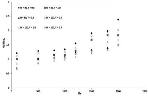
Figure 6 shows the Nusselt number ratio, Nu/Nu0, which is defined as the ratio of improved Nusselt number to Nusselt number of smooth channel plotted against the tested Reynolds number. The results indicate that with the increase of Reynolds number, the Nu/Nu0 ratios increases for wavy channel and almost all the values is greater than unity in higher Reynolds number range (above Re 1000). This effect can be clarified that the wave played a crucial role in increasing turbulence intensity. In lower Reynolds number (100-500) the significance of wave is not good than the higher Reynolds number range (above 1500). Also, one can see from the figure that the Nusselt number ratio for the case of small wave ratio and diameter ratio is the best one than the other test channels.
Figure 5. Average Nusselt number as a function of Reynolds number at different wave ratios and diameter ratios
Figure 6. Variation of Nu/Nu0 with Reynolds number at different wave and diameter ratios
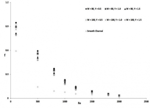
The effect of wavy channel on friction factor characteristics at different Reynolds number is presented in Figure 7. It could be obviously shown from Figure 7 that the friction factor continues to decrease with increasing Reynolds number. As predictable from Figure 7, the friction factors obtained from wavy channel were higher than those of the smooth channel. This was because of the swirl flow, secondary flow and recirculation; drag forces, and the turbulence intensity produced by the wave in the wavy channel. From Figure 7, one can also see that the channel with small wavy ratio have the highest friction penalty in low Reynolds number range but as the Reynolds number increase friction factor is almost same for all the cases.
Figure 8, represents the variation of friction factor ratio (f/f0) with Reynolds number for different wave ratio and diameter ratio in wavy channel. It was shown from Figure 8 that the friction factor ratios have a tendency to decrease with raising the Reynolds number for all the studied cases. Over the range examined, the friction factor ratios for the wavy channel are almost greater than unity.
Figure 7. Friction factor as a function of Reynolds number at different wave ratios and diameter ratios
Figure 8. Variation of f/f0 with Reynolds number at different wave and diameter ratios
The variation of thermal performance factor (η) with the Reynolds number is represented in Figure 9. The thermal performance factor was increased with the increase of Reynolds number for all the studied cases. The thermal performance analysis was achieved to assess the net energy increase of the entire tested wavy channel based on the constant blower power. It was found effective from an energy point of view. Almost all the tested wavy channel performance factors were greater than the unity above Re 1200. As expected from the wavy channel at higher Reynolds number provided higher thermal performance. For both of diameter ratios (W = 80.0 and 100.0), the small wave ratio (Y=0.5) give the best thermal performance factors than the other tested channels.
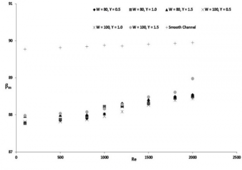
The core content of filed synergy principle revolves around the fact that improving the synergy between the velocity and the temperature gradient is the basic mechanism for enhancing convective heat transfer for a system. Therefore this analysis will help to realise the actual enhancement caused due to the presence wave. Major part of the flow domain is redistricted to synergy angle close to 90⁰. This is the reason the average synergy angle for each case is lies in the range of 87.5⁰ to 90⁰ as seen in Figure 10.
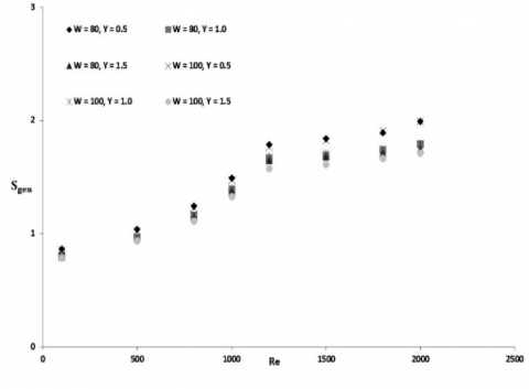
The total entropy generation rate is the amount of heat exchange irreversibly and fluid flow irreversibility with Reynolds number at different wave ratios. Figure 11 shows the variation of the total entropy generation rate per unit length with Reynolds number at different wave ratios and diameter ratio. The heat transfer irreversibility decreases with increasing Reynolds numbers and decreasing wave ratios. The figure shows existence of an optimal Reynolds number for which the total entropy generation (Sgen) is a minimum. So, it is clear that the use of high Reynolds numbers and low wave ratios is unfavorable to the thermodynamic performance of the channel.
Figure 9. Thermal enhancement factors as a function of Reynolds number and wave and diameter ratios
Figure 10. Comparison of average synergy angle at different wave and diameter ratios
Figure 11. Total entropy generation rates as a function of Reynolds number and wave and diameter ratios
The numerical investigation of heat and fluid-flows through a wavy channel is carried out, with the aim to examine the effect of wave ratio and diameter ratio on the flow, heat transfer and friction loss behaviors. The computational analysis show that the results are in good agreement with correlations. The synergy angle and entropy generation are also presented.
The obtained results show that, low wave ratio and low diameter ratio’s combined effect is showing some promising result in terms of heat transfer. The thermal performance factor of the wavy channel is influenced by the wave ratios (Y) and the best thermal performance factor at constant pumping power is found at clearance ratio, Y = 0.5.
Ao plain channel flow cross-sectional area
Dh internal diameter of the channel
f dimensionless friction factor
g acceleration due to gravity
Gr Grashof number
Gz Graetz number
hz axially local heat transfer coefficient
L axial length, length of the channel
m mass flow rate
Nu Nusselt number
⧍P pressure drop
P wetted perimeter
Pr Prandtl number
Re Reynolds number
Ra Rayleigh number
S Entropy
V velocity
Y wave ratio
Greek symbols
β Synergy angle
γ fluid thermal conductivity
v Kinematic viscosity
Subscripts
f bulk fluid
i inlet
m mean
o outlet
w channel wall
gen generation
[1] Webb, R.L., Kim, N.H., Principles of Enhanced Heat Transfer, second ed., Taylor & Francis, New York, 2005.
[2] Rush, T.A., Newell, T.A., Jacobi, A.M., “An experimental study of flow and heat transfer in sinusoidal wavy passages,” Int. J. Heat Mass Transfer, vol. 42, pp. 1541–1553, 1999.
[3] Mohamed, N., Khedidja, B., Belkacem, Z., Michel, D., “Numerical study of laminar forced convection in entrance region of a wavy wall channel,” Numer. Heat Transfer, Part A, vol. 53, pp. 35–52, 2008.
[4] Cheng, Y.P., Lee, T.S., Low, H.T., “Numerical analysis of periodically developed fluid flow and heat transfer characteristics in the triangular wavy fin-and-tube heat exchanger based on field synergy principle,” Numer. Heat Transfer, Part A, vol. 53, pp. 821–842, 2008.
[5] Heris, S.Z., Esfahany, M.N., Etemad, G., “Numerical investigation of nanofluid laminar convective heat transfer through a circular tube,” Numer. Heat Transfer, Part A, vol. 52, pp. 1043–1058, 2007.
[6] Heris, S.Z., Etemad, S.G., Esfahany, M.N., “Convective heat transfer of a Cu/water nanofluid flowing through a circular tube,” Exp. Heat Transfer, vol. 22, pp. 217– 227, 2009.
[7] Ge, T.S., Dai, Y.J., Wang, R.Z., Peng, Z.Z., “Experimental comparison and analysis on silica gel and polymer coated fin-tube heat exchangers,” Energy, vol. 35, pp. 2893e900, 2010.
[8] Bhattacharyya, S., Saha, S. K., “Thermohydraulics of laminar flow through a circular tube having integral helical rib roughness and fitted with centre-cleared twisted-tape,” Experimental Thermal and Fluid Science, vol. 42, pp. 154-162, 2012. DOI: 10.1016/j.expthermflusci.2012.05.002.
[9] Bhattacharyya, S., Saha, S., Saha, S.K., “Laminar flow heat transfer enhancement in a circular tube having integral transverse rib roughness and fitted with centre-cleared twisted-tape,” Experimental Thermal and Fluid Science, vol. 44, pp. 727-735, 2013.
[10] Saha, S.K., Bhattacharyya, S., Pal, P.K., “Thermohydraulics of laminar flow of viscous oil through a circular tube having integral axial rib roughness and fitted with center-cleared twisted-tape,” Experimental Thermal and Fluid Science, vol. 41, pp. 121-129, 2012.
[11] Saha, S.K., Bhattacharyya, S., Dayanidhi, G.L., “Enhancement of heat transfer of laminar flow of viscous oil through a circular tube having integral axial rib roughness and fitted with helical screw-tape inserts,” Heat Transfer Research, vol. 43, no. 3, pp. 207 – 227, 2012.
[12] Bhattacharyya, S., Chattopadhyay, H., “Computational of studies of heat transfer enhancement in turbulent channel flow with twisted strip inserts,” in: Proceedings of CHT-15, ICHMT International Symposium on Advances in Computational Heat Transfer, Rutgers University, Piscataway, USA, 2015.
[13] Bhattacharyya, S., Roy, A., Bhattacharyya, A., Dey, K., Seth, D., “Computational heat transfer analysis of a counter-flow heat exchanger with fins,” in: Proceedings of Recent Developments in Mechanical Engineering, Pune, 2015.
[14] Bhattacharyya, S., Chattopadhyay, H., Saha, S.K., “Numerical Study on heat transfer enhancement of laminar flow through a circular tube with artificial rib roughness,” J. Refrig, Air Conditioning, Heat. Ventilation, vol. 1, no. 3, pp. 14–19, 2014.
[15] [15] Bhattacharyya, S., Roy, A., Chattopadhyay, H., Rakshit, A., “A numerical investigation based on heat transfer and fluid flow characteristics of air in a circular tube heat exchanger with inclined ribs,” Proceedings of ICACE 2015, Recent Advances in Chemical Engineering, pp. 11-20, 2016. DOI: 10.1007/978-981-10-1633-2_2.
[16] Bhattacharyya, S., Chattopadhyay, H., Bandyopadhyay, S., “Numerical study on heat transfer enhancement through a circular duct fitted with centre-trimmed twisted tape,” International Journal of Heat and Technology, vol. 34, no. 3, pp. 401-406, 2016.
[17] Bhattacharyya, S., Chattopadhyay, H., Roy, A., A Rakshit, A., Chowdhury, I.R., “Thermohydraulic transport characteristics of micro mixer in micro channel,” Proceedings of ICACE 2015, Recent Advances in Chemical Engineering, pp. 29-39, 2016. 10.1007/978-981-10-1633-2_4.
[18] Bhattacharyya, S., Chattopadhyay, H., Pal, T.K., Roy, A., “Numerical investigation of thermohydraulics performance in elliptical twisted duct heat exchanger,” CAD/CAM, Robotics and Factories of the Future Part of the series Lecture Notes in Mechanical Engineering, pp. 839-849. DOI: 10.1007/978-81-322-2740-3_81.
[19] Bhattacharyya, S., Chattopadhyay, H., Benim, A.C., “Heat transfer enhancement of laminar flow of ethylene glycol through a square channel fitted with angular cut wavy strip,” Procedia Engineering, vol. 157, pp. 19–28, 2016. DOI: 10.1016/j.proeng.2016.08.333.
[20] Bhattacharyya, S., Chattopadhyay, H., Bandyopadhyay, S., Roy, S., Pal, A., Bhattacharjee, S., “Experimental investigation on heat transfer enhancement by swirl generators in a solar air heater duct,” International Journal of Heat and Technology, vol. 34, no. 2, pp. 191-196, 2016, DOI: 10.18280/ijht.340206.
[21] Bhattacharyya, S., Chattopadhyay, H., Pal, A., Bandyopadhyay, S., Roy, S., “Numerical simulation of fluid flow and heat transfer enhancement in a circular wavy channel,” Journal of Thermal Engineering and Applications, vol. 2, no. 2, pp. 28-35, 2015.
[22] Xie G.N., Wang Q.W., Sunden B., “Parametric study and multiple correlations on air-side heat transfer and friction characteristics of fin-and-tube heat exchangers with large number of large-diameter tube rows,” Appl Therm Eng, vol. 29, pp. 1-16, 2009.
[23] Tang L.H., Zeng M., Wang Q.W., “Experimental and numerical investigation on air-side performance of fin-and-tube heat exchangers with various fin patterns,” Exp Therm Fluid Sci, vol. 33, pp. 818-827, 2009.
[24] Torii K., Kwak K.M., Nishino K., “Heat transfer enhancement accompanying pressure-loss reduction with winglet-type vortex generators for fin-tube heat exchangers,” Int J Heat Mass Transfer, vol. 45, pp. 3795-3801, 2002.
[25] Zhang Y.H., Wu X., Wang L.B., Song K.W., Dong Y.X., Liu S., “Comparison of heat transfer performance of tube bank fin with mounted vortex generators to tube bank fin with punched vortex generators,” Exp Therm Fluid Sci, vol. 33, pp. 58-66, 2008.
[26] A. Joardar, A. Jacobi, A numerical study of flow and heat transfer enhancement using an array of delta-winglet vortex generators in a fin-and-tube heat exchanger, Journal of Heat Transfer, vol. 139, pp. 1156-1168, 2007.
[27] M. Gentry, A. Jacobi, “Heat transfer enhancement by delta-wing vortex generators on a flat plate: vortex interactions with the boundary layer,” Experimental Thermal and Fluid Science, vol. 14, pp. 231-242, 1997.
[28] M. Gentry, A. Jacobi, “Heat transfer enhancement by delta-wing-generated tip vortices in flat-plate and developing channel flows,” ASME Journal of Heat Transfer, vol. 124, pp. 1158-1168, 2002.
[29] W.Q. Tao, Numerical Heat Transfer, second ed., Xi’an Jiaotong University Press, Xi’an, 2001.
[30] Fan, A. W., Deng, J.J., Nakayama, A., and Liu, W, Parametric study on turbulent heat transfer and flow characteristics in a circular tube fitted with louvered strip inserts, International Journal of Heat and Mass Transfer, vol. 55, pp. 5205-5213, 2012.
[31] Gou, Z.Y., Tao, W.Q., Shah, R.K., “The field synergy (coordination) principle and its applications in enhancing single phase convective heat transfer,” International Journal of Heat and Mass Transfer, vol. 48, pp. 1797–1807, 2005.
[32] A. Bejan, Entropy Generation Minimization: the Method of Thermodynamic Optimization of Finite-Size Systems and Finite-Time Processes, CRC Press, Boca Raton, Fla., 1996.
[33] S.W. Churchill, H. Ozoe, “Correlations for laminar forced convection with uniform heating in flow over a plate and in developing and fully developed flow in a tube,” ASME J. Heat Transfer, vol. 95, pp. 78–84, 1973.