OPEN ACCESS
In the present work experiments were done on a modified LPG Diesel dual fuel engine with diesel as primary fuel and liquefied petroleum gas as secondary fuel by providing a venturi at the inlet manifold for better performance at all loading conditions. The engine was run at different operating conditions and in each case the optimum combination fuel energy proportions were determined for best efficiency. The exhaust smoke level, temperature, and other emission parameters were measured. The results were compared with the performance of the engine with diesel as sole fuel, and as dual engine without modifications and specific conclusions were then arrived. It was concluded that the brake thermal efficiency slightly reduces with modified design in comparison with conventional design. Diesel consumption is reduced considerably and also CO and HC emission are slightly higher at lower loads and reduces with increase in load. Smoke density and NOx are reasonably reduced in the modified design with LPG flow rate of 0.3 kg/hr found to be optimum in all conditions.
Dual Fuel Engine, Diesel Engine, Liquefied Petroleum Gas, Modified Gas Inlet.
Fossil fuels are the dominant global source of air pollution and their combustion is showing greater threat to clean environment. The economic cost of the effect of this pollution on human health and environment has been estimated at 0.4 % of gross domestic product [1, 2]. However, it is possible that in some areas the costs may be substantially higher. The limits for reduction in the emission levels of emission have been agreed [3] by various nations.
Gaseous fuels are capable of performing a prominent role to reduce emission. Various gaseous fuels such as biogas, producer gas, hydrogen, LPG and CNG (Compressed Natural Gas) are suitable for Internal Combustion Engines [4]. But LPG and CNG are considered better alternatives because of their simpler structure with low carbon content, resulting in reduction of exhaust emissions drastically [5]. When CNG was used as fuel in automobiles, it results in lower carbon monoxide and particulate matter emission as compared to diesel operation.
In India, LPG is easily available compared to CNG [6, 7]. Hence, for the present work LPG was taken as primary fuel. In dual fuel engine, the primary fuel releases large amount of energy and secondary fuel is required to start the combustion of the primary fuel [8]. The dual fuel engines are capable of switching from one fuel to the other without interruption in power generation [9].
The performance and emission of LPG-Diesel dual fuel engine is comparable with diesel operation at higher load [10]. The cycle variation on the performance of the LPG-Diesel dual fuel engine was found to be lower between the LPG flow rates of 0.2 to 0.3 kg/hr, fluctuations in various parameters like peak pressure, rate of pressure rise and indicated mean effective pressure was minimum [11, 12].
Phase equilibrium is a basis of calculation of enthalpy and entropy, and it is a clearly reveal of liquefied degree of raw natural gas [13, 14]. Main variables affecting the LPG-diesel dual engine are the LPG flow rate and diesel consumption. It is shown that there is an optimum LPG flow rate for maximum efficiency and also at lower loads LPG will not burn completely due to excessive lean mixtures. Higher secondary fuel quantity is to be used at low outputs to ensure proper combustion of the gaseous fuels [15, 16].
The secondary fuel LPG is premixed with the intake air and supplied to the engine. LPG duel fuel engines have a good thermal efficiency at high output but the performance is less during part load conditions due to the poor utilization of charges. This problem can be solved by varying injection timing, composition of the gaseous fuel and intake charge conditions, for improving the performance, combustion and emissions of dual fuel engines [17]. The objective of the present work is to develop a dual fuel engine test rig operating on LPG-diesel fuel with some modifications in the intake manifold for better mixing of the secondary fuel and to compare the engine performance characteristics without modifications and along with sole fuel.
In the present work, LPG was used as gaseous fuel in the dual fuel engine. The fuel properties of diesel fuel are shown in Table 1. The composition and properties of LPG are shown in Table 2. In the present work, an attempt was made to reduce the diesel engine emission using Liquefied Petroleum Gas (LPG) as a substitute for diesel. A single cylinder diesel engine test rig was modified to work in dual fuel mode. In dual fuel mode, LPG was used as gaseous fuel and diesel was used as the secondary fuel. For the present work, three LPG flow rates (0.3, 0.5, and 0.8 kg/hr) were considered.
Table 1. Properties of diesel
|
1. Flash Point |
56°C |
|
2. Fire Point |
63°C |
|
3. Calorific Value |
42.96 MJ/kg |
|
4. Kinematic Viscosity at 40° C |
2.68 cSt |
|
5. Density at 40°C |
828 kg/m3 |
Table 2. Composition and properties of LPG
|
Composition (by % Volume) |
|
|
N-Butane, Iso-Butane and Butyene |
70.4 % |
|
Ethane and Ethylene |
0.5 % |
|
Pentane |
47.88 |
|
Calorific Value |
2000 MJ/kg |
|
Maximum flame temperature in air |
525 °C |
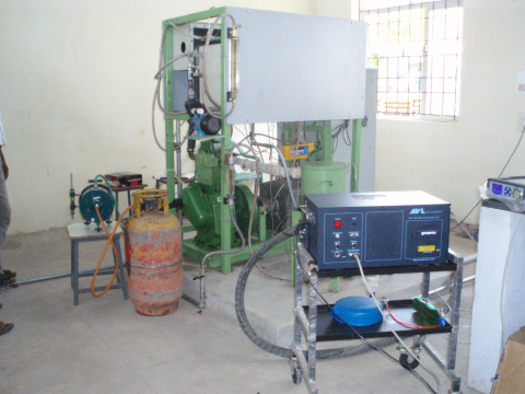
A single cylinder, four stroke, direct injection, water cooled diesel engine was used for conducting the experiments as shown in figure 3. The engine was modified to work in the dual fuel mode by attaching an LPG line to the intake manifold directly and through venturi of different size for better turbulence of the secondary fuel. The flow rate of LPG can be varied manually, and measured by a wet type gas flow meter.
The engine is connected to an eddy current dynamometer. It is provided with temperature sensors for measurement of jacket water inlet and outlet temperatures, pressure sensor for combustion pressure and encoder for crank angle measurements. Provision is also made for air and liquid fuel flow measurement. The LPG cylinder is connected to the inlet manifold through a rubber hose provided with a valve. The gas flow rate is measured by INSREF 06 wet type gas flow meter.
The set up enables study of indicated power, brake power, thermal efficiency, fuel consumption, air fuel ratio, heat balance, emission of CO,CO2,HC,O2 and Oxides of Nitrogen.
The experiments were carried out in four different phases. These were neat diesel, then by directly admitting LPG in to the intake manifold at the flow rate of 0.3, 0.5 and 0.8 kg/hr along with diesel. The experiments were repeated by providing a venturi attachment of three different diameters (20, 15 and 12mm).
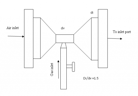
Figure 1. Modified intake manifold
Table 3. Engine details
|
Type |
Single Cylinder, Vertical, Four Stroke, Constant Speed (1500 rpm), Direct Injection, Water Cooled Diesel Engine |
|
Bore x Stroke |
87.5 x 110 mm |
|
Cubic Capacity |
0.553 litre |
|
Compression Ratio |
17.5 : 1 |
|
Rated Output |
4.4 kilowatts |
|
Injection Timing |
23.4 degree bTDC |
|
Loading Type |
Eddy Current Dynamometer |
|
Torque |
28 N-m |
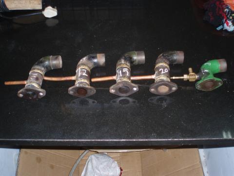
Figure 2. Venturi attachments of three different diameters
The dual fuel engine was started by hand cranking with diesel as fuel and slowly LPG was introduced into the cylinder through the air intake manifold. The LPG flow rate was adjusted to 0.3 kg/hr and the engine speed was maintained at 1500 rpm. At no load and at steady state condition, important observations such as diesel flow rate, air flow rate, exhaust gas temperature and exhaust emissions were recorded. Then the load was increased up to full load for the increment of 25%. Similar procedure was followed for the LPG flow of 0.5 and 0.8 kg/hr.
Figure 3. Schematic diagram of dual fuel setup
Experiments were conducted to compare the performance and emission of diesel and then by injecting the secondary fuel LPG in to the intake manifold at the flow rate of 0.3, 0.5 and 0.8 kg/hr along with diesel with and without intake manifold modifications and data recorded are presented here.
Figure 4. Carbon monoxide with load for different flow of LPG and sole diesel fuel
Figure 4 shows that the Carbon monoxide emission is reduced from 0.14 % to 0.06 % by volume from no load to full load in the case of diesel fuel. But in the cases of 0.3kg/hr, 0.5kg/hr and 0.8kg/hr flow of LPG gas, the values of carbon monoxide on higher side, at rated output 0.22 %, 0.16 % and 0.16 % by volume respectively. The values of carbon monoxide are increased with increase in load. At rated output 0.3kg/hr flow rate of LPG shows less carbon monoxide emission. The 0.8kg/hr flow rate of LPG shows higher carbon monoxide emission values at loading conditions. The emission rates are little high in the modified design comparing with the conventional dual fuel engine.
Figure 5. Hydrocarbon with load for different flow of LPG and sole diesel fuel
Figure 6. Oxides of nitrogen with load for different flow of LPG and sole diesel fuel
Figure 5 shows that the variation of hydrocarbon with load for the three flow conditions and also sole diesel fuel. At no load the HC values are higher for all flow rate of LPG compared with diesel. Since the secondary fuel LPG also contains C and H atoms and also the presence of oxygen is less during initial engine start period. As the load increases the value of HC reduces and at the rated power output 0.3kg/hr,0.5kg/hr flow of LPG, shows the same HC values of sole diesel fuel. Among the flow rate 0.8kg/hr shows higher value of HC compared to the other flow rate and as well as sole diesel fuel.
Figure 6 shows that the variation of oxides of nitrogen with load. The values of NOx are very less at not load and increases along with load. At rated power output sole diesel fuel shows higher NOx emission compared with other LPG flow conditions. All the three flow conditions of LPG show almost the same value of NOx. But at part load conditions the 0.8kg/hr flow of LPG shows less NOx emission compared with the other conditions. The fuel contains more oxygen or the percentage of air is more, the formation of NOx will also be more. Since LPG also consists of C and H atoms the formation of NOx is highly reduced at all loading conditions.
Figure 7 shows the variation of indicated thermal efficiency with load. At rated power output the indicated thermal efficiency of sole diesel fuel, 0.3kg/hr, 0.5kg/hr and 0.8kg/hr flow of LPG is 52%, 43%, 37% and 29% respectively. Diesel shows higher indicated thermal efficiency compared to all other value of flow rate of LPG. The 0.8kg/hr flow rate of LPG shows less efficiency compared to other flow rates.
Figure 7. Indicated thermal efficiency with load for different flow of LPG and sole diesel fuel
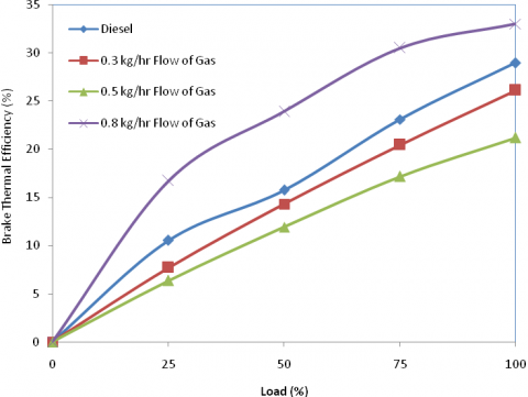
Figure 8. Brake thermal efficiency with load for different flow of LPG and sole diesel fuel
Figure 8 shows the variation of brake thermal efficiency with load. At rated power output the brake thermal efficiency of sole diesel fuel, 0.3kg/hr, 0.5kg/hr and 0.8kg/hr flow of LPG is 28.98%, 26.1%, 21.21% and 33.04% respectively. The LPG flow rate of 0.8kg/hr shows higher brake thermal efficiency than the other flow rates. The 0.5kg/hr flow rate of LPG shows less brake thermal efficiency compared to all other value of flow rate of LPG. At part loads 0.3kg/hr flow of LPG and sole diesel fuel indicates almost same values.
The increase in LPG flow rate reduces the NOx emissions. The value of NOx is very less during no load conditions for all flow of LPG and also sole diesel fuel conditions. From the above analysis it is found that 0.3kg/hr LPG with Diesel fuel delivering optimum condition with lower CO and HC emissions and slightly higher NOx.
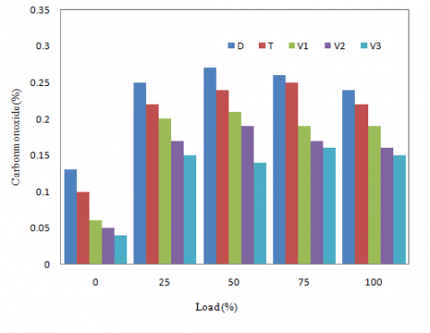
In the following figures D represent diesel fuel without modification (using the present method of T Joint), T represents 0.5kg/hr flow of LPG without modification of intake manifold, V1 represents intake modified with venturi of V1=di/dv = 40 /12, V2 represents intake modified with venturi of V2=di/dv =40 /15 and V3 represents intake modified with venturi of V3=di/dv = 40/20. Where di represents LPG and air outlet diameter, dv represents LPG and air inlet diameter as shown in figure 1.
Figure 9. Carbon monoxide with load for different intake manifold with 0.3 kg/hr LPG with diesel
Figure 10. Hydrocarbon with load for different manifold with 0.3 kg/hr LPG with diesel
Figure 11. Oxides of nitrogen with load for different manifold with 0.3kg/hr LPG with diesel
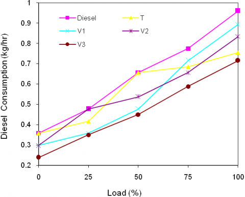
Figure 12. Diesel consumption with load for different manifold with 0.3 kg/hr LPG with diesel
From the figure 10, 11 and 12 it is found that V3 configuration show good reduction in carbon monoxide and NOx emissions. Figure 12 show that the diesel consumption is less in the case of V3 venturi configuration compared to the other configurations.
From this analysis, it is observed that diesel consumption is reduced considerably by using the modified venturi configuration. The design of venturi configuration is optimized by comparing all the configurations tested. Carbon monoxide values are reduced considerably using 0.3kg/hr LPG flow with V3 venturi. But in the case of hydro carbon the emission are little high at low loads and is reduced with increase in load. NOx are reasonably reduced in the modified design. V3 design with LPG flow rate of 0.3 Kg/hr was found to be optimum in all conditions.
|
LPG |
Liquefied Petroleum Gas |
|
CO |
Carbon Monoxide |
|
HC |
Hydrocarbon |
|
NOx |
Oxides of Nitrogen |
|
CNG |
Compressed Natural Gas |
|
CO2 |
Carbon Di-oxide |
|
O2 |
Oxygen |
|
ppm |
Parts-per million |
|
bTDC |
Before Top Dead Centre |
|
N-m |
Nanometre |
ANNEXURE
Consolidated Results for Different Flow Rate of LPG with Diesel and Sole Diesel Fuel
|
|
Diesel |
0.3 kg/hr LPG flow |
0.5 kg/hr LPG flow |
0.8 kg/hr LPG flow |
|
Carbon monoxide |
0.07 |
0.15 |
0.22 |
0.23 |
|
Hydrocarbon |
46 |
125 |
203 |
282 |
|
Oxides of Nitrogen |
778 |
520 |
546 |
446 |
|
Indicated Thermal Efficiency |
51.79 |
45.43 |
40.92 |
33.25 |
|
Brake Thermal Efficiency |
33.04 |
28.98 |
26.11 |
21.21 |
Consolidated Results for 0.3kg/hr Flow Rate with Different Configuration of Venturi
|
|
T |
V1 |
V2 |
V3 |
|
Carbon monoxide |
0.15 |
0.19 |
0.16 |
0.15 |
|
Hydrocarbon |
125 |
118 |
109 |
105 |
|
Oxides of Nitrogen |
520 |
606 |
642 |
515 |
|
Indicated Thermal Efficiency |
45.43 |
47.35 |
46.12 |
48.4 |
|
Brake Thermal Efficiency |
28.98 |
30 |
27.03 |
30.08 |
[1] Lelieveld, J. Evans, J. S. Fnais, M. Giannadaki and D. Pozzer, A., “The contribution of outdoor air pollution sources to premature mortality on a global scale,” Nature, vol. 525, September 2015. DOI: 10.1038/nature15371.
[2] Sierens R. R. and Rosseel E. E., “Variable composition hydrogen/natural gas mixtures for increased engine efficiency and decreased emissions,” ASME. J. Eng. Gas Turbines Power, vol. 122, no. 1, pp. 135-140, 1999. DOI: 10.1115/1.483191.
[3] Munde Gopal, G. and Dalu Rajendra, S., “Compressed natural gas as an alternative fuel for spark ignition engine: A review,” vol. 2, no. 6, pp. 92-96, 2012. http://www.ijeit.com/vol%202/Issue%206/IJEIT1412201212_16.pdf
[4] Reji Mathai, R. K. Malhotra, K. A. Subramanian and L. M. Das, “Comparative evaluation of performance, emission, lubricant and deposit characteristics of spark ignition engine fueled with CNG and 18% hydrogen-CNG,” International Journal of Hydrogen Energy, vol. 37, no. 8, pp. 6893-6900, April 2012. DOI: 10.1016/j.ijhydene.2012.01.083.
[5] R. S. Hosmath, Banapurmath, N. R., Khandal, S. V., Gaitonde, V. N., Basavarajappa, Y. H. and Yaliwal, V.S., “Effect of compression ratio, CNG flow rate and injection timing on the performance of dual fuel engine operated on honge oil methyl ester (HOME) and compressed natural gas (CNG),” Renewable Energy, vol. 93, August 2016, Pages 579-590, ISSN 0960-1481, DOI: 10.1016/j.renene.2016.03.010.
[6] Prabhahar M., Murali Manohar and Sendilvelan S., “Performance and Emission characteristics of diesel engine with various injection pressures using biodiesel,” Indian Journal of Science and Technology, vol. 5, no. 6, pp. 2880-2884, 2012. Available: http://www.indjst.org/index.php/indjst/article/view/30480
[7] Prabhahar M., Murali Manohar and Sendilvelan S., “Performance, emission and characteristics of a direct injection diesel engine with pongamia methyl ester and diesel blends,” European Journal of Scientific Research, vol. 73, no. 4, pp. 504-511, 2012.
[8] A. E. Dhole, R. B. Yarasu and D. B. Lata, “Investigations on the combustion duration and ignition delay period of a dual fuel diesel engine with hydrogen and producer gas as secondary fuels,” Applied Thermal Engineering, vol. 107, pp. 524-532, August 2016. DOI: 10.1016/j.applthermaleng.2016.06.151.
[9] Silvana Di Iorio, Agnese Magno, Ezio Mancaruso, and Bianca Maria Vaglieco, “Characterization of particle number and mass size distributions from a small compression ignition engine operating in diesel/methane dual fuel mode,” Fuel, vol. 180, Pages 613-623, September 2016. DOI: 10.1016/j.fuel.2016.04.108.
[10] Jeftić M. and Zheng M., “Postinjection strategy for the reduction of the peak pressure rise rate of neat n-Butanol combustion,” ASME. J. Eng. Gas Turbines Power, vol. 138, no. 9, 2016. DOI: 10.1115/1.4032765.
[11]Sudhir. C.V., Vijai Desai, Suresh Kumar. V. and Mohanan P., “Performance and emission studies on the effect of injection timing and diesel replacement on a 4-s LPG-Diesel dual fuel engine,” SAE 912366, pp. 966, 1991. DOI: 10.4271/2003-01-3087. http://papers.sae.org/2003-01-3087/
[12] Karim, G. A., “An examination of some measures of improving the performance of gas fuelled diesel engine at light load,” SAE 912366, 1991. DOI: 10.4271/912366.
[13] Li S. Zhang, Y. D. Li, and R. Q. Liao, “Equilibrium calculation and technological parameters optimization of natural gas liquefaction process with mixed refrigerant,” International Journal of Heat and Technology, vol. 33, no. 2, 2015. DOI: 10.18280/ijht.330220.
[14] Poonia M. P., Ramesh, A. and Gaur, R.R., “Effect of intake air temperature and pilot fuel quantity on the combustion characteristics of a LPG-diesel dual fuel engine,” SAE 1998-SP1391. DOI: 10.4271/982455. http://papers.sae.org/982455/.
[15] Poonia, M. P., Ramesh, A. and Gaur. R. R., “Experimental investigation of the factors affecting the performance of a LPG – Diesel dual fuel engine,” SAE, 1999-SP1412. DOI: 10.4271/1999-01-1123. http://papers.sae.org/1999-01-1123/.
[16] Chaabane, R. Askri, F. and Ben Nasrallah, S., “The fuel mixtures of gasonine-alcohols and their influence on air and water,” International Journal of Heat and Technology, vol. 29, no.2, pp. 21-24, 2001. Available: http://www.iieta.org/Journals/H%26TECH/ARCHIVE/Volume%2029%20No%202
[17] Sforzo, B., Dao, H., Wei and Seitzman, J., “Liquid fuel composition effects on forced, non-premixed igniton,” ASME. J. Eng. Gas Turbines Power, 2016. DOI: 10.1115/1.4034502.
[18] Ashok, B., Denis Ashok, S. and Ramesh Kumar, C., “LPG diesel dual fuel engine – A critical review,” Alexandria Engineering Journal, vol. 54, no. 2, Pages 105-126, June 2015. DOI: 10.1016/j.aej.2015.03.002.