OPEN ACCESS
In consideration of the characteristics of vapor-liquid-solid three-phase fluidized bed, this evaporator is applied in the liquid food-green tea extraction liquid concentration/evaporation process in this paper. The inert particles fluidized bed evaporation experiment device is designed and built combined with the characteristics of food material concentration. In this experiment, the heat transfer mechanism and hydrodynamic performance of inert particles fluidized bed evaporator during extraction of concentrated green tea are studied, and the impact of various experimental operation parameters on the evaporation and heat transfer performance as well as pressure dropping is analyzed. Moreover, the dimensionless analysis method is used to establish a correlation formula between the heat transfer coefficient and pressure drop dimensionless number of inert particle fluidized bed evaporator according to the characteristics of inert particles fluidized bed. In addition, the fouling prevention and descaling property and hydrodynamic performance of inert particle fluidized bed evaporator are studied, providing practical significance for industrial production.
Heat transfer mechanism, Vapor-liquid-solid three-phase fluidized red, Particle fluidized bed.
Evaporation/boiling heat transfer is a significant method of heat transfer involved in various industries and technological fields. Vacuum evaporation is a mature liquid food concentration method that is widely used at present. So it is important to provide a suitable evaporator and appropriate operating conditions for liquid food [1]. As for liquid food evaporation and concentration, there will be scaling problems of varying degrees on the wall of the evaporation/boiling side due to precipitation of dissolved materials in the liquid, condensation of protein and other reasons. The scale layer increases the wall surface thermal resistance and fluid flow resistance and reduces the heat exchange efficiency, and also directly affects the product quality, worsens the food color, smell, taste and favor. Excessively high heat flux leads to partial overheating of the wall surface or even damages the whole heat exchanger [2-4]. Furthermore, the fouling greatly affects the material and operation of the heat transfer equipment. Therefore, the enhanced heat transfer, fouling prevention and descaling technologies of liquid food evaporation equipment have attracted increasing attention from researchers.
D.G.K laren, R.R autenbaeh, et al. have developed a liquid-solid fluidized bed heat exchanger. The heat transfer wall can remain clean for a long period and the heat transfer coefficient can be improved to a large degree in a serious scaling condition. The vapor-liquid-solid three-phase fluidized bed evaporator is a new evaporation equipment developed in recent years [5-8]. As for this type of evaporator, the inert solid particles are added in a traditional evaporation tube to realize the vapor-liquid-solid three-phase boiling heat transfer in the evaporation tube. The evaporator is featured with good descaling effect and high heat transfer coefficient, and it has already been used in the field of seawater desalination. However, the study and report of this kind of evaporator in food material concentration is lacking [9-12].
In consideration of the characteristics of vapor-liquid-solid three-phase fluidized bed, this evaporator is applied in the liquid food-green tea extraction liquid concentration/evaporation process in this paper. The inert particles fluidized bed evaporation experiment device is designed and built combined with the characteristics of food material concentration [13]. In this experiment, the heat transfer mechanism and hydrodynamic performance of inert particle fluidized bed evaporator during extraction of concentrated green tea are studied, and the impact of various experimental operation parameters on the evaporation and heat transfer performance as well as pressure dropping are analyzed [14]. Moreover, the dimensionless analysis method is used to establish a correlation formula between the heat transfer coefficient and the pressure drop dimensionless number of inert particle fluidized bed evaporator according to the characteristics of inert particles fluidized bed. In addition, the fouling prevention and descaling property and hydrodynamic performance of inert particle fluidized bed evaporator are studied, providing practical significance for industrial production.
The calculation formulas for convection heat transfer are:
$\frac{1}{K}=\frac{1}{\alpha^{\prime}}+R_{s 1}+\frac{b}{\lambda} \frac{D_{t}}{D}+R_{s 2}+\frac{1}{\alpha} \cdot \frac{D_{1}}{D}$(1)
where, K is total heat transfer coefficient, w/(m2×K);
a` is convection heat transfer coefficient of flow outside tube, w/(m2×K); a is convection heat transfer coefficient of flow inside tube, w/(m2×K); Rsl is fouling resistance outside the tube wall, m2×K/w; Rs2 is fouling resistance inside the tube wall, m2×K/w; Dt is tube external diameter, m;
D is tube internal diameter, m;
b is tube thickness, m;
λis thermal conductivity coefficient of tube, W/(m×K).
As for the inert particle fluidized bed evaporator, the formula of vapor condensation heat transfer coefficient outside the tube has already become mature. The fouling resistance at the external and internal sides of the tube wall can be obtained through the experience data, and it is not difficult to obtain the conductive thermal resistance of the wall surface [15-18]. However, the boiling heat transfer coefficient formula for inert particle fluidized bed evaporator is not mature at present, and the experimental study on the boiling heat transfer coefficient of inert particle fluidized bed evaporator will be carried out this paper.
2.1 Three-phase flow heat transfer model
For the three-phase flow heat transfer model, many researchers have studied the vapor-liquid-solid three-phase flow system, having obtained different empirical correlations according to the operation parameters, mainly including two types. Among them, one is in dimensionless number form, and the other is in parameter form.
(1) Dimensionless number form
EN. ZIEGLO have studied the heat transfer performance of liquid-solid two-phase flow and three-phase fluidized bed, assuming the liquid content is constant in the three-phase flow and two-phase flow systems by setting the example of glass particle and column Y-particle. Then the three-phase flow and two-phase flow heat transfer coefficient should be expressed by thermal resistance of fluidized bed [20-24]. The result is that the three-phase fluidized bed heat transfer coefficient and the corresponding liquid-solid two-phase fluidized bed heat transfer coefficient can be obtained by the following correlation formula:
$S t_{m 3}=S t_{m 2}=0.127 \mathrm{Re}_{m 2}^{0.354} \mathrm{Pr}^{-0.362} U_{R}^{0.266} \phi s^{-1}$(2)
$S t_{m 2}=\frac{h_{2} \varepsilon_{L 2}}{\rho_{L} C_{p L} \mu_{L}}$(3)
$S t_{m \overline{3}}=\frac{h_{3} \varepsilon_{L 3}}{\rho_{L} C_{p L} \mu_{L}}$(4)
$\operatorname{Pr}=\frac{C P_{L} \mu_{L}}{\lambda_{L}}$(5)
$\operatorname{Re}_{m 2}=\frac{u_{L} \rho_{L}}{s\left(1-\varepsilon_{L 2}\right) \mu_{L}}$(6)
$\frac{h_{2}}{C P_{L} \rho_{L} \mu_{L}}=\frac{h_{2} d_{p}}{k}\left(\frac{u_{L} d_{p} \rho_{L}}{\mu_{L}}\right)^{-1}\left(\frac{C p_{L} \rho_{L}}{k}\right)^{-1}$(7)
According to Eq. (2) ~ (7),
$N u_{2}=\frac{h_{2} d_{p}}{k}=0.762 \mathrm{Re}_{m 2}^{0.646} \mathrm{Pr}^{0.638} u_{R}^{0.266} \phi_{s}^{-1} \frac{1-\varepsilon_{L 2}}{\varepsilon_{L 2}}$(8)
For $S t_{m 3}=S t_{m 2}$ Then,
$h_{3} \varepsilon_{L 3}=h_{2} \varepsilon_{L 2}$(9)
$N u_{3}=\frac{h_{3} d_{p}}{K}=0.763 \mathrm{Re}_{m 2}^{0.646} \mathrm{Pr}^{0.638} u_{R}^{0.266} \phi_{s}^{-1} \frac{1-\varepsilon_{L 2}}{\varepsilon_{L 2}}$(10)
As for the vapor-liquid-solid three-phase boiling heat transfer system, the above assumption cannot be combined with the real situation because the liquid vaporization and steam rate accounts for a large proportion, thus the heat transfer correlation cannot be directly applied to boiling heat transfer.
(2)Parameter form
O.N oREandG, et al. have studied the vapor-liquid-solid three-phase heat transfer coefficient under low particle density with the following correlation formula:
$h=2390 u_{L}^{\beta} u_{G}^{x}\left(\rho_{s}-\rho_{1}\right)^{\delta} d_{p}^{\gamma} \varepsilon_{s}^{1-\beta}$(11)
wherein:
$\beta=1-1.958\left(\rho_{p}-\rho_{L}\right)^{-0.253}$(12)
$x=1.791\left(\rho_{p}-\rho_{L}\right)^{-0.364} \delta$(13)
$\gamma=0.55-1.958\left(\rho_{p}-\rho_{L}\right)^{-0.253}$(14)
As for the above two forms, the inert gas will be added to meet the research condition by means of electric heating. It is largely different from vapor-liquid-solid three-phase flow during heating of the steam, and the parameter form is also different from the actual operation parameters [25-29]. To summarize, the vapor-liquid-solid three-phase boiling and heat transfer are also studied.
2.2 Vapor-liquid-solid Three-Phase Flow Boiling and Heat Transfer Model
For the vapor-liquid-solid three-phase flowing and boiling with solid particles, there is little literature related to heat transfer model. Currently, the two-phase flow boiling heat transfer formula is applied to the three-phase flow system based on Chen's dual-mechanism theory to summarize and modify the two-phase flow model, wherein the basic form can be classified as the summation model, asymptotic model and reinforcement model.
It is explicitly expressed in Chen's model that among flow boiling, the two mechanisms including nucleate boiling and convection heat transfer come into action at the certain proportion respectively for each. Furthermore, the contribution of the two heat transfer modes varies in accordance with the improvement of flow condition. Chen's expression for two-phase flow boiling and heat transfer is:
$h=S h_{n b}+h_{t}$(15)
where, h is two-phase flow saturated boiling and heat transfer coefficient, w/(m2×K);
Hnbis nucleate boiling and heat transfer coefficient, w/(m2×K)
hlis-convection heat transfer coefficient of single flow, w/(m2×K);
S is nucleate boiling inhibitor
Chen's extended expression for three-phase flow boiling and heat transfer is:
$h_{f b s}=\left[\left(E h_{l s}\right)^{n}+\left(S_{s} h_{n b, s}\right)^{n}\right]^{\frac{1}{n}}$(16)
where, hfos is heat transfer coefficient for three-phase flow boiling , w/( m2×K);
E is three-phase convection heat transfer enhancer, dimensionless
Ss is three-phase nucleate boiling inhibitor, dimensionless
hls is liquid-solid two-phase flow heat transfer coefficient, w/( m2×K)
hnb,sis nucleate boiling and heat transfer coefficient with solid particles, w/( m2×K)
When n = 1, the model is the summation model; when n = 2, the model is the asymptotic model; and when n = 3, the model is the reinforcement model.
When large-scale industrial equipment is designed based on the model parameters obtained from a small device, the flow pattern of the two devices will be consistent with first. The flow characteristics of the three-phase flow based on the experimental observation are described, and the model for expressing the inside tube structure model is put forward. The three-phase boiling heat transfer is classified based on the characteristics of the inside tube and vapor-fluid exchange mechanism combined with the flowing substance status. The liquid belongs to the continuous phase while the solid and vapor belongs to the dispersed phase [30]. The flow pattern mainly relies on the fluid flow, nature of fluid and particles, as well as the evaporator structure, gas production rate and other factors. The turbulent motion of solid particles and liquid can break bubbles, and large bubbles will be broken due to the addition of solid particles, in which most of the flow area consists of a bubbly flow [31-34]. When the particle volume fraction is small with a large amount of produced bubbles, the bubbles will coalesce, while when the amount of particles is large under full fluidization, the bubble will be dispersed.
The fluidization of particles of in fluidized bed evaporator basically consists of the following three interrelated processes. Firstly, the fluid passes through t he fluidized bed and inert particles layer. Secondly, the inert particles are separated from each other due to the fluid action to realize the fluidization of the particles layer. Thirdly, the status between inert particles and fluid is well maintained. In the experiment, the stabilization of the fluidized state during the operation process will be mainly considered, thus the third process is the most important. In the below, the change rule of flow resistance in tubes of inert particle fluidized bed evaporator will be studied [35-39].
The pressure drop in the evaporation tube has the following parameters: fluid apparent velocity μ1, vapor apparent flow velocity ug, flow medium density pl, viscosity μ1, inert particles diameter dp, flow inert particle density ps, gravity acceleration g, in-tube height H, fluidized bed diameter D, and solid particles content εs. The general expression for the pressure drop of inert particle fluidized bed evaporator tube is listed thorough dimensional analysis:
$f\left(\Delta P, g, u_{1}, \rho_{1}, \mu_{1}, D, \rho_{s}, d_{p}, H, u_{g}, \varepsilon_{s}\right)=0$(17)
In Eq. (17), there are in total 11 parameters, wherein, εs is dimensionless, and there are 10 physical quantities involving three basic dimensions; i.e., length L, quality M, and time θ. According to the principle of the second theorem, the dimensionless number in dimensionless analysis is equal to the difference between variable number n and basic dimensionless number m, or, n-m=10-3=7. When the six dimensionless numbers are π1, π2, π3, π4, π5, π6 and π7, the Eq. (17) can be transferred into dimensionless form as:
$\phi\left(\pi_{1}, \pi_{2}, \pi_{3}, \pi_{4}, \pi_{5}, \pi_{6}, \pi_{7}\right)=f\left(\varepsilon_{s}\right)$(18)
The new measuring units m/cl, s/c2 and Kg/c3 are used to transfer the Eq. (38) into dimensionless form, then,
$f(\Delta Pc_3c1^{-1}c_2^{-2},u_1c_1c_2^{-1},ρ_1c_3c_1^{-1},\mu_1c_3c_2^{-1}c_1^{-1},Dc_1,gc_1c_2^{-2},Hc_1,\epsilon_s,u_gc_1c_2^{-1})=0$ (19)
To convert the equation above into a dimensionless equation, let:
$D c_{1}=1, \mathrm{c}_{1}=\frac{1}{D}$(20)
$\rho_{1} c_{3} c_{1}^{-3}=1, c_{3}=\frac{c_{1}^{3}}{\rho_{L}}=\frac{1}{D^{3} \rho_{1}}$(21)
$\mu_{1} c_{3} c_{1}^{-1} c_{2}^{-1}=1, c_{2}=\mu_{1} c_{3} c_{1}^{-1}=\frac{\mu_{1}}{D^{2} \rho_{L}}$(22)
Insert Eq. (20)- (22) into Eq. (19)
$\pi_{1}=\Delta P c_{3} c_{1}^{-1} c_{2}^{-2}=\frac{\Delta P \rho_{l} D^{2}}{\mu_{l}^{2}}$(23)
$\pi_{2}=u_{1} c_{1} c_{2}^{-1}=\frac{\rho_{l} D_{c} u_{l}}{\mu_{l}}=\operatorname{Re}_{l}$(24)
$\pi_{3}=u_{v} c_{1} c_{2}^{-1}=\frac{\rho_{l} D_{c} u_{g}}{\mu_{l}}=\mathrm{Re}_{v}$(25)
$\pi_{4}=d_{p} c_{1}=\frac{d_{p}}{D}$(26)
$\pi_{5}=H c_{1}=\frac{H}{D}$(27)
$\pi_{6}=g c_{1} c_{2}^{-2}=\frac{g D^{3} \rho_{l}^{2}}{\mu_{l}^{2}}$(28)
$\pi_{7}=\frac{\rho_{s}}{\rho_{l}}$(29)
The following six dimensionless groups are obtained by arranging and merging Eq. (23)~(29);
$\frac{\Delta P}{\rho_{l} u_{l}^{2}}=E u$(30)
$\frac{\rho_{l} D u_{l}}{\mu_{l}}=\operatorname{Re}_{l}$(31)
$\frac{H d_{p}}{D^{2}}$(32)
$F r=\frac{u_{1}^{2}}{g D}$(33)
$\frac{\rho_{s}-\rho_{l}}{\rho_{l}}$(34)
$\frac{\rho_{l} D u_{g}}{\mu_{l}}=\mathrm{Re}_{v}$(35)
$E u=C_{2} F r^{a} \operatorname{Re}_{1}^{\mathrm{h}} \operatorname{Re}_{\mathrm{v}}^{c}\left(\frac{H d_{p}}{D^{2}}\right)^{d}\left(\frac{\rho_{s}-\rho_{l}}{\rho_{l}}\right)^{c} \varepsilon_{s}^{t}$(36)
From Eq. (30) and Eq. (32), the empirical correlation formula of pressure drop in tubes of inert particle fluidized bed evaporator can be obtained:
$\Delta P=C_{2} \rho_{l} u_{l}^{2} F r^{a} \operatorname{Re}_{1}^{b} \operatorname{Re}_{v}^{c}\left(\frac{H d_{p}}{D^{2}}\right)^{d}\left(\frac{\rho_{s}-\rho_{l}}{\rho_{l}}\right)^{c} \varepsilon_{s}^{f}$(37)
Under heat, fluid of which the liquid mass flow is w entering the tube from the bottom and is heated by the heat flux q on the tube surface and gradually evaporates. In this case, steam velocity uG increases with the increase of distance z from a tube. Relevant liquid and steam mass flow at point Z can be obtained from the steam mass flow; i.e., steam content x. The steam content x can be calculated through thermal balance in a thermodynamic equilibrium state, and thereupon,
$W_{G}=W_{x}=M A_{1} x$(38)
$W_{L}=W(1-x)=M A_{1}(1-x)$(39)
where
M is mass velocity, Kg/s,
A1 is sectional area of the tube, m2
In a thermodynamic equilibrium state, the steam content can be calculated through thermal balance. According to the thermal balance, there is:
$q \cdot A=\gamma_{v} \cdot W_{G}+W \cdot \Delta i_{i}$(40)
It can be obtained from Eq. (40):
$q \cdot \pi D Z=\gamma_{v} \cdot W_{G}+W \Delta i_{i}$(41)
$x=\frac{W_{G}}{W}=\frac{1}{\gamma_{v}}\left(\frac{4 Z q}{D M}-\Delta i_{i}\right)$(42)
According to the definition of void fraction:
$\beta=\frac{A_{G}}{A}=\frac{1}{1+\frac{W_{L}}{W_{G}} \cdot \frac{\rho_{G} u_{G}}{\rho_{L} u_{L}}}$(43)
There is:
$\beta=\frac{1}{1+\frac{1-x}{x} \cdot \frac{\rho_{G} u_{G}}{\rho_{L} u_{L}}}$(44)
The particle phase is adopted to simulate the fluid model for the vapor-liquid-solid three-phase flow system, and the obtained conservation equation of three-phase flow is:
$\sum F=\sum_{i=1}^{3}\left(-\rho_{i} \alpha_{i} A g d x-\rho_{i} \alpha_{i} A d x \frac{d u_{i}}{d t}-\alpha_{i} A d_{p}-\alpha_{i} A d_{F R-1}+\sum_{j=1}^{3} \delta_{i j} W_{i j}\right)=0$(45)
The first right item in Eq. (45) refers to gravity, the second item force is acceleration, the third item is pressure, the fourth item is friction, and the fifth item is inter-phase interaction force. There is a formula in the fifth item as below:
$W_{i j}=-W_{j i}$(46)
If i=j, when,
And$\frac{d u_{i}}{d t}=u_{i} \frac{d u_{i}}{d x}$, Eq. (46) can be written in the following form:
$-\frac{d p}{d x}=\sum_{i=1}^{3}\left(-\rho_{i} \alpha_{i} g+\rho_{i} \alpha_{i} \frac{d u_{i}}{d x}+\left(\frac{d P}{d x}\right)_{F R-1}\right)$(47)
The above equation reveals that the pressure drop of vapor-liquid-solid three-phase flow is still composed of friction pressure drop, gravity pressure drop and acceleration pressure drop. For stable-state flow, the acceleration pressure drop can be disregarded [40-43].
In a single-phase flow system, according to the fanning equation, the friction factor is:
$\lambda=f\left(\operatorname{Re}_{l}, e / d\right)$(48)
The liquid phase Reynolds number Rel and vapor phase Reynolds number Re in Eq. (48) can be determined from Eqs. (43) and (48), reflecting the friction pressure drop during the three phases flow.
$A r=F r \operatorname{Re}_{l}^{2}\left(\frac{\rho_{s}-\rho_{l}}{\rho_{l}}\right)$(49)
4.1 Experiment contents
In the experiment, flow patterns are researched on an experimental facility of coated electric heating quartz glass tube, examining and analyzing the two phases of steam and liquid which are easy to scale under which working conditions and such flow patterns. Meanwhile, influences of the solid particle quantity on the flow pattern, flow characteristics and heat-transfer characteristics of vapor-liquid two-phase flow and the relation among fluid velocity, particle concentration and fluid height of particles in a fluidized bed evaporator provide a basis for the explosive evaporation operation conditions of the steel three-phase fluidized bed evaporator.
4.2 Steps of the process
(1) Add a certain number of solid particles in the three-phase fluidized bed evaporator system according to the demands of the experiment.
(2) Turn on the material system and steam vacuum pump to make the whole vaporization system be in a vacuum state.
(3) Turn on the electric heating quartz glass tube evaporator and control the heating electric power. As for the three-phase fluidized bed evaporator, turn on the heating boiler to make the boiler water temperature rise to boiling temperatures.
(4) Start up the feed pump and shut it down after the tea extract reaches the set liquid level in storage tank 7.
(5) Turn on the circulating pump, adjust the valve to make the liquid flow reach a certain value and then turn on the steam heating system, until the flow of heating steam is slightly larger than the material preheating. After the liquid boils, adjust the flow of heating steam and other operating parameters according to the experimental design table and record the data after the flow becomes stable. During an evaporation experiment with an electric heating quartz glass tube evaporator, the flow situation in the tube must be shooting.
(6) Change the quantity of solid particles and repeat the above-mentioned work.
(7) Firstly stop the steam heating after the experiment. Then close the valve after the liquid cools to a certain temperature and finally stop the circulating pump.
(8) Turn off and close the cooling water.
4.3 Results of the experimental
Tables 1 and 2 show the variance analysis of regression, where regression sum of squares refers to the total contributions of all factors to the change in the heat transfer coefficient, reflecting the importance of all factors. The error sum of squares reflects the influence of experiment errors and other factors that are not controlled. It can be seen from Eq. (8) and Table 2 that within the scope of the experiment of inert particle fluidized bed evaporator, Reynolds number Re1, dimensionless number group gas and volume fraction of solid particles εs obviously influence the heat transfer coefficient positively. Prandtl numeral P has a positive non-significant influence but negative significant influence. The influence of dimensionless density is not significant and PI is negative.
Table 1. Converted to ln (Nu) of multiple regression analysis of variance
|
Sources of variance
|
Degrees of freedom |
Sum of squares |
The mean square |
The F value |
Significance level |
|
Df |
SS |
MS |
F |
Sig |
|
|
Return analysis |
7 |
3.625 |
0.544 |
102.31 |
0.000 |
|
Error |
48 |
0.254 |
0.0059 |
|
|
|
The sum |
50 |
3.5845 |
|
|
|
Table 2. Heat transfer coefficient of the regression results of the analysis
|
Variable |
Numerical |
Standard deviation |
T test |
Significance |
|
C1 |
0.102 |
12.6 |
-0.178 |
0.847 |
|
A |
0.524 |
0.05 |
9.25 |
0.002 |
|
B |
0.269 |
0.05 |
6.25 |
0.001 |
|
C |
1.545 |
1.84 |
0.84 |
0.365 |
|
D |
-0.825 |
0.06 |
-12.3 |
0.000 |
|
E |
0.632 |
0.04 |
12.58 |
0.000 |
|
F |
-0.254 |
25.47 |
-0.02 |
0.941 |
It can be seen from Tables 1 and 2 that multiple correlation coefficient is R=0.969, fitting the multiple correlation coefficient is close to 1 and the linear regression effect is good. It can be seen from the significance that the influence of Re1 is the most significant, showing that the influences of heating condition in inert particle fluidized bed evaporators, flow condition of fluid, physical dimension of evaporators and added solid particles on the heat transfer coefficient is of greatest importance. As the physical parameters change of the tea extract adopted in the experiment is small under the experimental conditions, Pr is not significant. Influences of dimensionless density are not so significant (see Figure 1).
Figure 1. Heat transfer coefficient of the experimental value compared with the predicted value
It can be seen from Figure 2 that when other parameters are specified, the heat transfer coefficient of inert particle fluidized bed evaporator firstly increases and then decreases with the increase of liquid flow.
Figure 2. Influence of fluid flow on the heat transfer coefficient
In the inert particle fluidized bed evaporator, the liquid phase is a continuous phase. Inert particles and vapor are dispersed phases and the flow area of three-phase fluidized bed is decided by the flow rate of liquid. If the flow is small, the flow area will increase with the increase of flow.
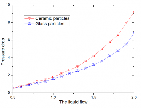
Figure 3. Liquid flow affect on pressure drop
Figure 3 shows that if the solid concentration and heat transfer rate are the same, the flow pressure drop of inert particle fluidized bed evaporator will increase with the increase of circulation flow of fluid. ΔP∝u2 can be obtained according to the formula of the flow pressure drop; i.e., the flow pressure drop increases with the increase of the flow rate of liquid. Furthermore, as the fluid flow increases, the friction between parties and fluid sharpens, collision rate increases, collision momentum increases and the drag force pressed on solid particles increases so that the fluid flow resistance increases, also increasing the acceleration pressure drop. In addition, with the increase of the flow rate of liquid, the flow in unit time increases, increasing the gravity pressure drop during the flow. The above-mentioned analysis shows that the increase in flow rate increases the flow pressure drop, gravity pressure drop and accelerates pressure drop. All the three aspects increase the pressure drop of the bed.
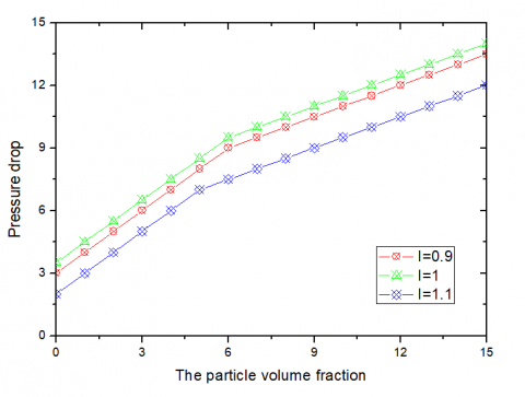
In the process of solid fluidization, solid particles are supported by the friction of fluid. With the increase of solid concentration, the friction between solids and fluid and between solids and walls increases and flow resistance increases, increasing the friction pressure drop. Furthermore, the volume fraction of solid particles increases, causing an increase in the flow mixed-phases density in the three-phase system, thus increasing the gravity pressure drop in the whole tube. Influences of the two aspects affect the flow pressure drop of inert particle fluidized bed evaporator and the trend of solid concentration increasing function (see Figure 4).
Figure 4. Particle integral rate affect pressure drop
Figure 5 shows that, compared with two-phase flow boiling heat transfer, the heat transfer coefficient of three-phase flow boiling heat transfer is obviously higher, because adding of particles increases evaporation cores, promotes the convection intensity of fluid at the heated wall surfaces and improves the thermal conduction properties of the working media. Due to this aspect, the heat transfer is strengthened, increasing the heat transfer coefficient. This is consistent with the heat transfer when solid particles float in boiling liquid researched by YuminYang; i.e., adding a small number of solid particles in boiling liquid can greatly improve the heat transfer performance of the coefficient. Meanwhile, if the particle sizes are the same, the higher the volume fraction of particles is, and the better the boiling heat transfer is. If the volume fraction of particles is specified, the smaller the particle is, the better the heat transfer performance Q is.
Figure 5. Three-phase circulating thermal coefficient compared with two-phase circulating thermal coefficient
In consideration of the characteristics of vapor-liquid-solid three-phase fluidized bed, this evaporator is applied in liquid food-green tea extraction liquid concentration/evaporation process in this paper. The inert particles fluidized bed evaporation experiment device is designed and built combined with the characteristics of food material concentration. In this experiment, the heat transfer mechanism and hydrodynamic performance of inert particle fluidized bed evaporator during extraction of concentrated green tea are studied, and the impact of various experimental operation parameters on the evaporation and heat transfer performance as well as pressure dropping is analyzed. Moreover, the dimensionless analysis method is used to establish a correlation formula between the heat transfer coefficient and the pressure drop dimensionless number of inert particle fluidized bed evaporator according to the characteristics of inert particles fluidized bed. In addition, the fouling prevention and descaling property and hydrodynamic performance of inert particle fluidized bed evaporator are studied, providing a practical significance for industrial production. This paper draws the following conclusions:
(1) Adding inert particles can strengthen the heat transfer. Three-phase flow boiling heat transfer coefficient is about 1.7 times of the two-phase flow boiling heat transfer coefficient.
(2) The heat transfer strengthening effect of solid particles is related to particle diameters, material and additional volume fraction. If the volume fraction is the same, the smaller the diameter is, and the better the heat transfer effect is. If the diameter is the same, the heat transfer effect will increase with an increase in volume fraction. Generally, when the volume fraction is 6%-12%, there will be a good effect of strengthening heat transfer and preventing and cleaning fouling.
(3) The experimental result shows that the tube wall temperature of inert particle fluidized bed evaporator is lower than that of 1-2°C when there is no particle in the evaporator, which is significant for treating heat sensitive materials.
This study was supported by the Natural Science Foundation of China (51309147 and 51249001) and Project of Shandong Province Higher Educational Science and Technology Program (J11LD22).
[1] Buchlin, J. M., “Convective heat transfer and infrared thermography (irth),”Journal of Applied Fluid Mechanics, vol. 3, no. 1, pp. 177-186, 2010.
[2] Lf, G., K, H. and Mj, T., “Wall imprint of turbulent structures and heat transfer in multiple impinging jet arrays,”Journal of Fluid Mechanics, vol. 546, no. 1, pp. 255-284, 2006.
[3] Hubble, David, O., Vlachos, Pavlos, P., Diller and Tom, E., “The role of large-scale vortical structures in transient convective heat transfer augmentation,” Journal of Fluid Mechanics, vol. 718, no. 3, pp. 89-115, 2013.
[4] Bloen, “Heat transfer across sheared suspensions: role of the shear-induced diffusion,” Journal of Fluid Mechanics, vol. 724, no. 2, pp. 527-552, 2013.
[5] Abdallah, M. S. and Zeghmati, B., “Natural convection heat and mass transfer in the boundary layer along a vertical cylinder with opposing buoyancies,” Journal of Applied Fluid Mechanics, vol. 4, no. 4, pp. 15-21, 2011.
[6] Prata, A. T. and Jr, J. R. B., “The Thermodynamics, heat transfer and fluid mechanics role of lubricant oil in hermetic reciprocating compressors,” International Conference on Heat Transfer, Fluid Mechanics and Thermodynamics, vol. 30, pp. 533-548, 2007.
[7] Spalart, P. R. and Strelets, Kh. M., “Mechanisms of transition and heat transfer in a, separation bubble.,”Journal of Fluid Mechanics, vol. 403, no. 2, pp. 329-349, 2000.
[8] Sp, S., “Vorticity amplification in stagnation-point flow and its effect on heat transfer,” Journal of Fluid Mechanics, vol. 21, no. 3, pp. 513-534, 1965.
[9] Bardet, P. M. and Peterson, P. F., “Options for scaled experiments for high temperature liquid salt and helium fluid mechanics and convective heat transfer,”Nuclear Technology, vol. 163, no. 3, pp. 344-357, 2008.
[10] Meyer, J. P., “Heat transfer, fluid mechanics, and thermodynamics in our environment—hefat2012,” Heat Transfer Engineering, vol. 35, no. 16-17, pp. 1141-1146, 2014.
[11] Garai, Kleissl Jan and Sarkar, Sutanu., “Flow and heat transfer in convectively unstable turbulent channel flow with solid-wall heat conduction,” Journal of Fluid Mechanics, vol. 757, no. 6, pp. 57-81, 2014.
[12] Chacon, O., Chacon, G. E. O. And Avelino, S. L. P., J., C., “Numerical modeling of fluid dynamics and heat transfer of glass flow in a short channel,” Brazilian Journal of Chemical Engineering, vol. 27, no. 4, pp. 663-675, 2010.
[13] Rocha, P. A. C. and Silveira, J. V. P. D., “Study and application of computational simulation in simple problems of fluid mechanics and heat transfer,”Revista Brasileira De Ensino De Física, vol. 34, no. 4, pp. 1-8, 2012.
[14] A. Mulder, A. A. van de Graaf, Robertson, L. A. and Kuenen, J. G., “Anaerobic ammonium oxidation discovered in a denitrifying fluidized bed reactor,” Fems Microbiology Ecology, vol. 16, no. 3, pp. 177–184, 1995.
[15] Tsuji, Y., Kawaguchi, T. and Tanaka, T., “Discrete particle simulation of two-dimensional fluidized bed,” Powder Technology, vol. 77, no. 1, pp. 79-87, 1993.
[16] Graaf, A. A. V. D., “Autotrophic growth of anaerobic ammonium-oxidizing micro-organisms in a fluidized bed reactor,” Microbiology, vol. 142, no. 8, pp. 2187-2196, 1996.
[17] Khan, A. A., Jong, W. D., Jansens, P. J. and Spliethoff, H., “Biomass combustion in fluidized bed boilers: potential problems and remedies,” Fuel Processing Technology, vol. 90, no. 1, pp. 21-50, 2009.
[18] Deen, N. G., Annaland, M. V. S., Hoef, M. A. V. D., and Kuipers, J. A. M., “Review of discrete particle modeling of fluidized beds,” Chemical Engineering Science, 62, no. 1–2, pp. 28-44, 2007.
[19] Wu, P. C. Z. Z. C., “Biomass gasification in circulating fluidized bed,” Restaurator, vol. 27, no. 3, pp. 178-185.
[20] Pengmei, L., Kong, X., Chuangzhi, W. U., Yuan, Z., Longlong, M. A., Chang, J., “Modeling and simulation of biomass air-steam gasification in a fluidized bed,” Chemical Engineering, vol. 2, no. 2, pp. 209-213, 2007.
[21] Schramm, A., De, B. D., Wagner, M., Amann, R., “Identification and activities in situ of nitrosospira and nitrospira spp. as dominant populations in a nitrifying fluidized bed reactor,” Applied & Environmental Microbiology, vol. 64, no. 9, pp. 3480-5, 1998.
[22] Bartels, M., Lin, W., Nijenhuis, J., Kapteijn, F., Ommen, J. R. V., “Agglomeration in fluidized beds at high temperatures: mechanisms, detection and prevention,” Progress in Energy & Combustion Science, vol. 34, no. 5, pp. 633-666, 2008.
[23] Lu, Y. J., Jin, H., Guo, L. J., Zhang, X. M., Cao, C. Q., Guo, X., “Hydrogen production by biomass gasification in supercritical water with a fluidized bed reactor,” International Journal of Hydrogen Energy, vol. 33, no. 21, pp. 6066-6075, 2008.
[24] Caneghem, J. V., Brems, A., Lievens, P., Block, C., Billen, P., Vermeulen, I., et al., “Fluidized bed waste incinerators: design, operational and environmental issues,” Progress in Energy & Combustion Science, vol. 38, no. 4, pp. 551-582, 2012.
[25] Graaf, A. A. V. D., Bruijn, P. D., LA Robertson, M. S. M. Jetten, Kuenen, J. G., “Metabolic pathway of anaerobic ammonium oxidation on the basis of 15 n studies in a fluidized bed reactor,” Microbiology (UK), vol. 143, no. 7, pp. 2415-2421, 1997.
[26] Ning, Y., Wei, W., Wei, G., Li, J., “CFD simulation of concurrent-up gas–solid flow in circulating fluidized beds with structure-dependent drag coefficient,” Chemical Engineering Journal, vol. 96, no. 1-3, pp. 71-80, 2003.
[27] Danafar, F., Fakhru’L-Razi, A., Salleh, M. A. M., Biak, D. R. A., “Fluidized bed catalytic chemical vapor deposition synthesis of carbon nanotubes—a review,” Chemical Engineering Journal, vol. 155, no. 1–2, pp. 37-48, 2009.
[28] De, V. G. A. A., “Metabolic pathway of anaerobic ammonium oxidation on the basis of n-15 studies in a fluidized bed reactor,” Microbiology, vol. 143, pp. 2415-2421, 1997.
[29] Hoef, M. A. V. D., Annaland, M. V. S., Deen, N. G., Kuipers, J. A. M., “Numerical simulation of dense gas-solid fluidized beds: a multiscale modeling strategy,” Annual Review of Fluid Mechanics, vol. 40, no. 1, pp. 47-70, 2008.
[30] Makkawi, Y. T., Wright, P. C. (“Fluidization regimes in a conventional fluidized bed characterized by means of electrical capacitance tomography,” World Congress on Particles Technology, vol. 57, pp. 2411-2437, 2002.
[31] Patil, D. J., Annaland, M. V. S., Kuipers, J. A. M., “Critical comparison of hydrodynamic models for gas–solid fluidized beds—part ii: freely bubbling gas–solid fluidized beds,” Chemical Engineering Science, vol. 60, no. 1, pp. 73-84, 2005.
[32] Mikami, T., Kamiya, H., Horio, M., “Numerical simulation of cohesive powder behavior in a fluidized bed,” Chemical Engineering Science, vol. 53, no. 10, pp. 1927-1940, 1998.
[33] Yao, W., Fei, W., Luo, G., Hao, Y., Gu, G., “The large-scale production of carbon nanotubes in a nano-agglomerate fluidized-bed reactor,” Chemical Physics Letters, vol. 364, no. 5-6, pp. 568-572, 2002.
[34] Senadeera, W., Bhandari, B. R., Young, G., Wijesinghe, B., “Influence of shapes of selected vegetable materials on drying kinetics during fluidized bed drying,” Journal of Food Engineering, vol. 58, no. 3, pp. 277-283, 2003.
[35] Tsuneda, S., Nagano, T., Hoshino, T., Ejiri, Y., Noda, N., Hirata, A., “Characterization of nitrifying granules produced in an aerobic upflow fluidized bed reactor,” Water Research, vol. 37, no. 20, pp. 4965-4973, 2003.
[36] Heo, H. S., Park, H. J., Park, Y. K., Ryu, C., Dong, J. S., Suh, Y. W., et al., “Bio-oil production from fast pyrolysis of waste furniture sawdust in a fluidized bed,” Bioresource Technology, vol. 101, Suppl 1, no. 1, pp. S91–S96, 2009.
[37] And, C. H. S., Harris, A. T., “A review of carbon nanotube synthesis via fluidized-bed chemical vapor deposition,” Industrial & Engineering Chemistry Research, vol. 46, no. 4, pp. 997-1012, 2007.