OPEN ACCESS
Large-scale LNG-FSRU is a new kind of storage and transportation facility for liquefied natural gas (LNG). It adopts the double hull double row tank structure, and the temperature distribution is quite complex. This paper utilizes a simplified analytical method and a finite element numerical method to analyze the steady thermal field of this large cargo area while transporting the ultra low temperature LNG. Eventually, the steady temperature field distribution of the cargo area is obtained. This study indicates that the analysis results of the simplified analytical method is consistent with that of the finite element numerical method in terms of the thermal field of double hull double row tank structural cargo area.
Double hull double row tank structure, Simplified analytical method, Finite element numerical method, Steady thermal field.
As a relatively economical and environmentally friendly alternative energy source, the status of natural gas (NG) is becoming increasingly prominent. Due to the rapid growth of consumption of NG, the demand for the maritime storage and transportation device is significantly raised as well. As a new NG storage device, LNG-FSRU can not only transport NG as a LNG carrier, but also conduct air feed as a NG receiving terminal. Compared to the traditional onshore receiving terminal, FSRU has a short construction period, a small occupied land area and high flexibility. In recent years, the research on the LNG storage and transportation device has been an issue of concern [1].
Hull structure is deformed with changes in temperature. Specifically, owing to the presence of structural constraints or the effect of temperature gradients, structural elements will produce a thermal effect, which impacts the strength and stability of the structure. The deck and side plating above the water are exposed to air in a temperature of 20-40℃. However, the external bottom and side plating below the surface of the hull are in the water maintaining a temperature of approximately 0-5℃ [2]. Accordingly, there exists an uneven temperature field of the hull structure as a result of the effects of the environment. In the analysis of structural strength of the hull, the temperature effect is normally regarded as an uncertainty implied in the permissible stress and safety coefficient without requiring special considerations. Furthermore, a detailed temperature field analysis of the hull is needed with regard to the special ship transporting the ultra-low temperature cargos (such as LNG carriers).
LNG carriers require a thermal insulation blanket for heat preservation and insulation while conveying LNG due to the extremely low temperature of the LNG (-162℃) [2]. Meanwhile, the LNG carriers normally adopt the double hull structure in order to prevent environmental pollution caused by a possible liquid cargo spill caused by a collision or grounding. The gunwale cabins between the double hulls and double bottom tanks full of air will have a thermal insulation effect on the high-temperature cargos. However, the internal and external hulls in this structure are in different mediums respectively, thus increasing the temperature gradient between the members. The yield strength and ultimate strength of the steels will be raised at low temperatures. Conversely, its plasticity will be lowered, which means that it is prone to brittle fractures. Simultaneously, the low temperature will affect the fatigue properties of the steel. In this case, ultra-low-temperature liquid cargos would not only drastically increase the temperature gradient of the double hulls, bringing significant additional temperature stress to the hull elements, but also will affect the overall safety of the structure. Hence, it is necessary to analyze the temperature field of the hull structure carrying the ultra-low temperature liquid cargos.
The analysis of the temperature field is widely used in the area of petrochemical industry, dynamic, nuclear energy and so forth. The general large scale structural analysis programs, such as NASTRAN, ABAQUS, can be utilized for such analysis, but there is limited study into the temperature field distribution of the double row hull structure transporting ultra low temperature liquid cargo (Hu Yu-ren [3], Li Pin-you [4], Teng Xiao-qing [5], Lin Hao [6]). By constructing an ideal mathematical model and utilizing thermodynamic analytical formulae, the temperature field distribution of different parts of the hull structure can be analyzed. However, this method is currently only used for LNG ships with relatively simple structures. Zhang Wei-xing [7] studied the temperature field of LNG carrier based on the ANSYS software; Ding Shi-feng [8] exploited the computation module by utilizing the general finite element software to acquire the best coupling coefficient in various temperatures and various distances between the outer and inner hulls. W.B. Shi [9] studied the additional thermal stress of the hull structure brought by daily temperature field on the stance of raising the precision of the strain gauge of the hull girder.
This paper analyzes the steady temperature field distribution of a double hull double row tank structure in ultra-low temperature. It also utilizes both a simplified analytical method and a finite element numerical method to calculate the temperature field of the cargo area at the ultra-low temperature of -162℃ and conducts a comparison.
The analytic target is a LNG-FSRU with a volume of 270,000m3 ,with a principal dimensions $L_{P P} \times B \times D \times T=336.0 \mathrm{m} \times 58.0 \mathrm{m} \times 27.5 \mathrm{m} \times 12.0 \mathrm{m}$.
Additionally it adopts the double hull double row tank and longitudinally framed structure for the cargo area.
2.1 Assumptions and simplifications of the cargo area temperature field model
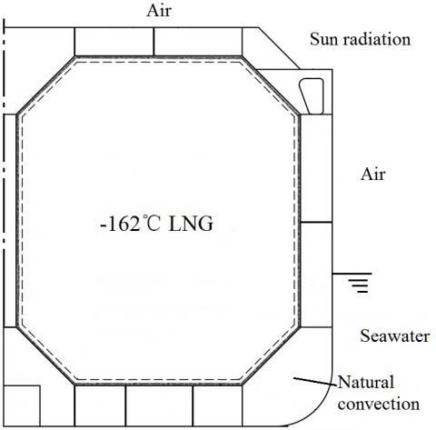
In terms of the convective heat transfer between hull plates and the external environment, also to be considered are the natural convection and the forced convection. Specifically, the former assumes the static air or sea in the external environment, while the latter considers the outside wind speed or velocity as shown in Figure 1.
Figure 1. 1/2 hull across section
The assumptions of temperature field analysis in cargo area are:
(1) Various cargo are fully loaded with ultra-low temperature liquefied natural gas (-162 ℃), and gunwale, bottom, longitudinal and transverse bulkhead components are all empty.
(2) The temperature of LNG remains constant and its temperature distribution is uniform during the transportation process. The ambient temperature also remains constant.
(3) The temperature field of cargo is steady, which would not change over time.
There are three basic modes of heat transfer: heat conduction, convection, and radiation heat transfer. The heat transfer occurs when the large LNG carriers utilize the effect of air and sea convection in movement, namely solar heat radiation. In this paper, the amount of computations would be greatly increased considering all the modes of heat transfer. Given that the distribution of the temperature field is mainly studied, the conditions of heat transfer would be simplified, ignoring the solar radiation. Specifically, in regard to the double hull double row tank structure, there are several modes of thermal transfer as follows:
(1) The convective heat transfer between the ship hull above the waterline and the air.
(2) The convective heat transfer between the ship hull below the waterline and the sea line.
(3) Heat conduction inside the structure.
(4) The natural convective heat transfer between the hull structure and the air in the double hull space.
(5) The natural convective heat transfer between the hull structure and the air in the double hull space.
(6) The heat exchange between the insulating layer and the inner shell.
The ambient temperature is not unified as it can change anytime anywhere, and this paper refers to the IGC conditions to conduct calculations [10].
2.2 The establishment of a mathematical model
In practice, the inner heat transfer of LNG carrier’s insulated hold is a complex and unsteady heat transfer process. However, the heat transfer process of the insulated hold could be equivalent to a steady heat transfer process according to relevant literature [7], thus allowing a comparatively precise calculation to be obtained.
In terms of general three-dimensional thermal transfer, the differential equation of steady heat transfer is as follows.
$\frac{\partial}{\partial x}\left(k_{x} \frac{\partial \phi}{\partial x}\right)+\frac{\partial}{\partial y}\left(k_{y} \frac{\partial \phi}{\partial y}\right)+\frac{\partial}{\partial z}\left(k_{z} \frac{\partial \phi}{\partial z}\right)+\rho Q=0$ (1)
$\left.\phi\right|_{s_{s}}=\phi^{e}$ (2)
$\left.k_{n} \frac{\partial \phi}{\partial n}\right|_{s_{2}}=q$ (3)
Where , $\rho$ is material density;
$k_{x}$, $k_{y}$, $k_{z}$ are thermal conductivities corresponding to three main directions ($x, y, z$) of Cartesian coordinate axis;
$Q$ is inner heat source density inside;
$n_{x}$, $n_{y}$, $n_{z}$ are the directions cosine on the boundary normal;
$\phi$ is objective temperature;
$\phi^{e}$is ambient temperature on the surface of $S_{1}$;
$q$ is the given heat flux density on the boundary of $S_{2}$;
$k_{n}$ is the material thermal conductivity perpendicular to the surface;
Equation (1) is valid inside the object and Equations (2), (3) are valid on the surface.
2.3 The simplifications of multi-layered screen bulkhead and the treatment of structural stiffener
The plating composed of different materials is referred to as multi-layered bulkhead. The heat conduction analysis of multi-layered bulkhead is to acquire corresponding temperature distribution through heat conduction analysis for each layer. Regarding the multi-layered bulkhead whose heat conduction coefficient is a constant, its temperature distribution should show in a broken line. Thus, the multi-layered bulkhead could be simplified as a one layered entity. According to heat conservation theorem, the thermal conductivity for multi-layered bulkhead is calculated as below.
$k=\frac{\sum_{i} \delta_{i}}{\sum_{i} \frac{\delta_{i}}{k_{i}}}$ (4)
The inner hull of the liquid cabin is made up of a two layered membrane; one layer of wooden boxes and one layer of resin. The thermophysical properties of these materials are shown in Table 1. Thereby the thickness of the inner hull is $0.561 m$ and the thermal conductivity is $0.0423(\mathrm{W} / \mathrm{m} \cdot \mathrm{K})$.
Table 1. The physical properties of materials
|
Name/Sequence |
Thickness (mm) |
Thermal conductivity $k(W / m \cdot K)$ |
|
INVAR |
0.7 |
48 |
|
Insulated Wooden Box |
230 |
0.04 |
|
INVAR |
0.7 |
48 |
|
Insulated Wooden Box |
300 |
0.04 |
|
Resin Layer |
10 |
0.302 |
|
Plate of Inner Hull |
15~22 |
48 |
In terms of such large scale structure of the ship’s cabin, there are a variety of stiffeners with different shapes and sizes, which directly affects the convection coefficient, thus affecting the overall heat transfer. When establishing the model, building out these stiffeners completely will increase the workload and expend much time. Hence the stiffeners require simplification in order to obtain an accurate result in terms of temperature field analysis. Specifically, the impact of stiffeners on the overall heat transfer is directly equivalent to the change of convection coefficient within the internal and external hulls.
2.4 The calculation for convective heat transfer coefficient in the process of convective heat transfer
When computing the temperature field of LNG-FSRU, the natural convection heat transfer is in the enclosed cabin between internal and external hulls [11] [12]. In this condition, the accurate calculation of convective heat transfer coefficient is a key for research on the temperature field. The general criterion formula for natural convection is as follows:
$h=\int\left(\rho g \beta \Delta l, l, \rho, \mu, c_{p} k\right)$ (5)
where, $\rho, \mu, c_{p} k$ reflects the influence of physical properties; $l$ embodies the effect of geometric characteristics; $\rho g \beta \Delta t$ expresses the impact of fluid buoyancy.
In terms of the natural convection of the perpendicular plate, the convective coefficient could be computed in the following formula:
$h=\frac{N_{u L} \cdot k}{L}$ (6)
where,
$N_{u L}$ is the Nusselt number, $N u_{L} \propto R a_{L}^{-n}$ ;
$R a_{L}$ is the fluid Raleigh number;
$L$ is the structural characteristic length.
In such a large scale structure of the hull, due to various cabin space sizes, there exists natural convection in not only a large space but also an enclosed space [13]. When calculating the convection coefficient for various areas, selected feature lengths differs.
3.1 The analysis based on the simplified analytical model
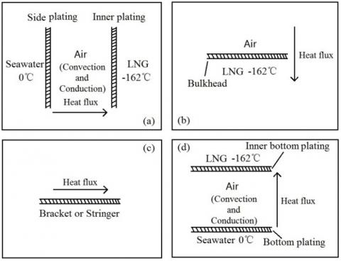
The temperature field of the cargo area is three dimensional, thus heat transfers in the longitudinal, lateral and vertical directions at the same time. Nevertheless, heat transfers mainly in a specific direction in the partial area. The thermal field of the cargo area would be simplified to four basic one-dimensional calculation models, as shown in Figure 2.
According to heat transfer theory, the thermal conduction differential equation of one-dimensional steady heat transfer without an inner heat source could be simplified as follows:
$\frac{d^{2} t}{d x^{2}}=0$ (7)
There are two main boundary conditions for four fundamental models of Figure 2:
(1) Given temperature distribution on the objective boundaries.
(2) Given conditions of heat exchange between object surface and surrounding fluid.
$h\left(t_{w}-t_{f}\right)=-\left.k \frac{\partial t}{\partial n}\right|_{w_{w}}$ (8)
Where, $t$ is temperature; $t_{w}$ is temperature of structural wall; $t_{f}$ is ambient temperature; $n$ is the outer normal direction of the boundary.
Figure 2. Fundamental one-dimensional calculation models of temperature field
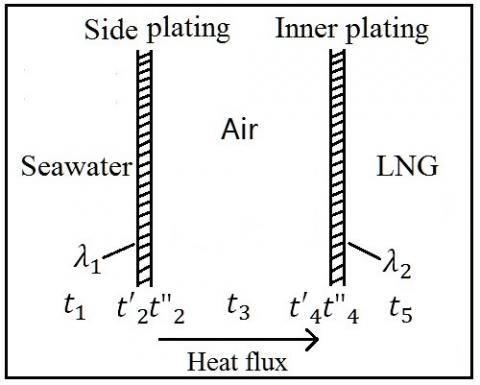
As an instant, the following thermal equation can be established based on the fundamental model of Figure 2 (a), referring to Figure 3.
Figure 3. The sample of the calculation model
$\left\{\begin{array}{l}q=h_{c}\left(t_{1}-t_{2}^{\prime}\right) \\ q=\frac{k_{1}}{W_{1}}\left(t_{2}^{\prime}-t_{2}^{\prime \prime}\right) \\ q=h_{i}\left(t_{2}^{\prime \prime}-t_{3}\right) \\ q=h_{i}\left(t_{3}-t_{4}^{\prime}\right) \\ q=\frac{k_{2}}{W_{2}}\left(t_{4}^{\prime}-t_{4}^{\prime \prime}\right) \\ q=h_{s}\left(t_{4}^{\prime \prime}-t_{5}\right)\end{array}\right.$ (9)
where,
$q$ is heat flux in unit area;
$h_{c}$ is convective heat transfer coefficient of sea;
$h_{i}$ is convective heat transfer coefficient of air;
$h_{s}$ is convective heat transfer coefficient of liquid cargo;
$k_{1}$ is convective heat transfer coefficient of outer side plate;
$k_{2}$ is convective heat transfer coefficient of inner side plate;
$W_{1}$ is thickness of outer side plate;
$W_{2}$ is thickness of inner side plate;
$t_{1}$ is temperature of sea;
$t_{2}^{\prime}$ is lateral temperature of outer side plate;
$t_{2}^{\prime \prime}$ is medial temperature of outer side plate;
$t_{3}$ is air temperature of gunwale cabin;
$t_{4}^{\prime}$ is lateral temperature of inner side plate;
$t_{4}^{\prime \prime}$ is medial temperature of inner side plate;
$t_{5}$ is temperature of liquid cargo.
The temperature of the inner and outer side plates can be determined through the solution of the above equations.
3.2 The analysis of finite element numerical method
Solving such coupling problems with a numerical method, the unitary computation approach is commonly used, that is, the heat transfer processes in different domains are combined as a unified heat excahnge process. In terms of the complex structure, the shortcoming of a unitary computation approach is to have a heavy modeling workload and slow convergence, which may not actually converge. In this case, the domain decomposition method and boundary coupling method are adopted.
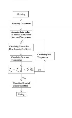
Firstly, the temperature of the atmosphere and the sea water should be input. Assuming the initial temperature of steel plates $T_{s}$ , the convection coefficient $h$ would be calculated and then the temperature distribution of each ship plate and heat insulation material layer $T_{n}$. If the temperature distribution of the ship plate does not satisfy the fomula:
$\sum\left|T_{n}-T_{n-1}\right|<0.01$ (10)
Then the above computation process would be repeated. Here $T_{n}$ is the calculated temperature of steel plates, and $T_{n-1}$ is the result of the previous step. The calculation process is shown in Figure 4.
Figure 4. Flowchart of thermal analysis
The LNG-FSRU ship normally uses a corrugated bulkhead in the cargo area, so it has a comparatively complex structure. In order to facilitate analysis and comparison, a simplified model is applied for the cargo area temperature field analysis, which means that the model is a combination of 1/2 cabin + vertical and horizontal bulkhead + 1/2 cabin. In addition, the longitudinal, beam, ribbed plate and girder are simulated in accordance with reality [14]. In the model, the insulating materials in the cargo area are simulated by 8-node solid elements, and the other hull members are simulated by plate and beam elements. Convective heat transfer is defined in the form of boundary conditions in the corresponding shell element.
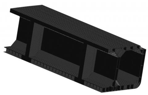
This paper uses large-scale and common finite element software, such as MSC/PATRAN, MSC/NASTRAN, as tools to build the finite element model of heat transfer in above cargo area (Figure 5) and conduct the calculation analysis for temperature field as well.
Figure 5. The finite element model of temperature field
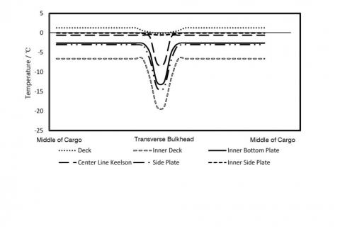
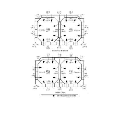
Relying on the above two methods, the temperature field of the cargo area would be computed. It is demonstrated that the temperature distribution along the longitudinal line of the main members in the cargo area is calculated using the finite element numerical method in Figure 6. With the purpose of studying the influence of structure on temperature distribution, the heating measures are not adopted in the transverse compartment and the middle of the longitudinal compartment. It is clear that horizontal bulkhead has a great influence on the inner hull and longitudinal structure (the difference is about 10℃), but has little influence on the longitudinal temperature field distribution of the outer hull. Thus, the heat exchange of the cargo area mainly occurs in the cross section. Moreover, the calculation result of the temperature field using the finite element numerical method and simplified analytical method are both illustrated in Figure 6. It can be seen from Figure 7:
Figure 6. Temperature distribution of main members in the longitudinal direction
(1) On the assumption of a uniform temperature field, the difference between the calculations of a finite element numerical method and simplified analytical method is negligible as the biggest difference is approximately 2.2℃.
(2) In the simplified analysis, temperature values at the intersection of each member cannot be determined according to this method assuming that each plate is infinitely large.
(3) Not considering the radiation heat transfer, the computing result for the inner deck temperature from both simplified analytical method and finite element numerical method are partial to conservative. However, the calculation of the inner deck temperature from the previous literature [14] [15] [16] is generally higher than from GTT statistics. Thus it can be seen that not considering radiation heat transfer is reasonable for determining the minimum designed temperature of the hull elements.
Figure 7. The calculation results of the temperature field(The numerical value with bracket is the results of the simplified analytical method)
This paper takes a certain LNG-FSRU ship with a volume of 270,000m3 as an objective to discuss some technical issues in detail, namely the assumptions and simplifications of the temperature field model, thermophysical properties parameters of the insulating layer, the calculation of thermophysical parameters in the heat transfer and the difference between the various calculation methods of the temperature field. On this basis, the calculation results of temperature field using the simplified analytical method and the finite element method are compared and analyzed to obtain the following conclusions:
(1) Heat transfer is a complex physical phenomenon. In this case, a large number of simplifications and assumptions are still required even with a large scale program for analysis.
(2) The temperature of cargo transported by LNG carriers is ultra-low, which is significantly different from the outside temperature. This paper utilized the temperature prescribed by IGC conditions to analyze the temperature field. Under this circumstance, the conclusion can be qualitatively applied to other temperature field analysis, including other high and low temperature field with a large inside and outside temperature difference.
(3) The analysis for temperature field of cargo area based on the finite element numerical method is consistent with that based on a simplified analytical method. Therefore, there is reason to believe that both finite element numerical method and simplified analytical method are feasible. In particular, the simplified analytical method might be adopted in the initial stage of conceptual design.
1. Jiang Tao, A Study of the Berthing Plan and Design of LNG Floating Storage And Re-Gasification Unit, Master thesis, Dalian Maritime University, Dalian, 2012.
2. Ding Shi-feng, Research on Structure Safety of Large LNG Carrier under Ultra-low Temperature, Ph.D. thesis, Shanghai Jiao Tong University, Shanghai, 2010.
3. Chen Bo-zhen, Hu Yu-ren, The Temperature Distribution and Thermal Stress Analysis of Ship Struetures, Journal of Shanghai Jiaotong University, vol. 29, no. 3, pp. 33-41, 1995.
4. Li Pin-you, On the Pre-cooling Temperature of Spherical Cargo Tank for MOSS Type LNG Carrier, Journal of Shanghai Maritime University, vol. 17, no. 1, pp. 73-78, 1996.
5. Teng Xiao-qing, Gu Yong-ning, Steady Temperature Distribution and Thermal Stress Analysis for Double Hull Structure, Shipbuilding of China , vol. 41, no. 2, pp. 58-65, 2000. DOI: 10.3969/j.issn.1000- 4882.2000.02.009.
6. Lin Hao, Heat Transfer Analysis of LNG Carrier’ s NO. 96 Cargo Containment System, Master thesis, Shanghai Maritime University, Shanghai, 2006.
7. Zhang Wei-xing, Li Ke-jun, Zhou Hao and Liu Chuntu, Study on Temperature Field for Mem-Brane Type Lng Carriers, Natural Gas Industry, vol. 25, no. 10, pp. 110-112, 2005. DOI: 10.3321/j. issn:1000- 0976.2005.10.037.
8. DING Shi-feng, TANG Wen-yong, ZHANG Sheng-kun, Research on Heat Transfer Simulation of Air in Closed Space for LNG Tanker, Ship & Ocean Engineering, vol. 38, no. 3, pp. 4-7, 2009. DOI: 10.3963/j.issn.1671- 7953.2009.03.002.
9. Shi W. B., Thompson, P. A. and Le Hire, J.-C., Thermal Stress and Hull Stress Monitoring, Transactions-Society of Naval Architects and Marine Engineers, vol. 104, pp. 61-79, 1996.
10. IMO, International Code for the Construction and Equipment of ships Carrying Liquefied Gases in Bulk (IGC Code), 1993 Edition, London: IMO, 1993.
11. Sarma, P. K. and Kishore, P. S., et al, A Method to Estimate Turbulent Natural Convection Heat Transfer to Air from a Vertical Plate, International Journal of Heat and Technology, vol. 21, no. 2, pp. 139-146, 2003.
12. Lorente, S., Lacarrière, B. and Lartigue, B., Influence of the Geometry on Heat Transfer by Natural Convection in a Rectangular Cavity, International Journal of Heat and Technology, vol. 20, no. 2, pp. 75- 80, 2002.
13. King, A. J. C. and Narayanaswamy, R., Radiative Effects on Natural Convection Heat Transfer in an Enclosure with Multiple Partitions, International Journal of Heat and Technology, vol. 27, no. 2, pp. 3-9, 2009.
14. ZHENG Xuan-liang, LIN Yan, CHEN Ming, FE Modeling Method and Its Program Realization of Ship Corrugated Bulkhead Based on ANSYS, Ship Engineering, vol. 29, no. 5, pp. 23 -26, 2007. DOI: 10.13788/j.cnki.cbgc.2007.05.006.
15. Zhou Hao, A Study of Convection Coefficient in LNG Ship’s Cavity, Master thesis, Beijing University of Chemical Technology, Beijing, 2006.
16. LI Bo-yang, LI Di-yang, Simulation and Analysis of Temperature Field in an Insulated Cabin of Membrane Type LNG Carrier, Navigation of China, vol. 31, no. 4, pp. 352 -355, 2008. DOI: 10.3969/j.issn.1000- 4653.2008.04.009.