OPEN ACCESS
To explore the forming mechanism of cold roll-beating forming technology, the parameters of the Johnson–Cook (J-C) dynamic constitutive equation for 40Cr are determined using experimental methods. Using the finite element software ABAQUS and tracking of the key node temperature we simulate both the temporal temperature distribution and the equivalent stress and strain distributions with and without consideration of the thermal effects of the 40Cr high-speed cold roll-beating forming process. The predicted flow stress based on the constitutive equations and the real stress are compared with the experimental data. Based on these comparisons, the true stress calculated based on the model and the predicted flow stress are both consistent with the experimental data. The dynamic constitutive model presented in this paper can effectively predict plastic flow stress for 40Cr quenched and tempered steel under various temperatures and the model also provides the theoretical basis for the further assessment of the thermal mechanical coupling effects of 40Cr high-speed cold roll-beating forming process.
Cold roll-beating, Thermal mechanical coupling, Johnson–Cook constitutive equation.
With increasing marketing competition and the rapid updating of products, many drawbacks associated with the traditional die forming process are day by day becoming more apparent, such as long production preparation time, large tonnage equipment, poor processing flexibility and high manufacturing costs [1]. Because of the excellent features of partial production, various advanced precise plastic forming technologies have become important research topics in modern technology. Light weight technology which is rapid, flexibile and precise is one of the main research targets in the new field of plastic forming [2-3]. As a near net shaped advanced manufacturing technology, cold roll-beating is of great interest as a dieless unconstrained incremental forming technology [4].
The theoretical studies on cold roll-beating started early in Europe and the U.S.. During the mid-1970s, the Polish scientist Marciniak founded the WPM method. The method used a pair of sector gears as forming tools, with the use of two eccentric shafts to ensure the circular motions of sectoral hobs to envelope the gear profile. The axial contacting arc between the tool and gear blank is longer, the relative sliding velocity is smaller and the tool life is longer [5]. Subsequently, Krapfenbauer proposed a new cold roll-beating technique called the Grob method, in which two pairs of rollers eccentrically mounted strike the workpiece surface and form gears or splines using an indexing motion [6-7]. At present, western countries have cold roll-beating machine tools, high-speed cold roll forming technology, and research results from conducted studies. However, few reports exist based on the core technology.
Research on cold roll-beating technology in China began in the 1970s. Currently, the objects of study mainly included spline, screws, plates, and other materials. Furthermore, rolling wheel design theory, kinematics, dynamics, forming mechanisms, and other aspects of high speed cold roll-beating forming technology were studied and led to initial research results [8-11]. At present, however, the study of cold roll-beating is still in the exploration and development stage A system has not yet been formed for the theory and practice.
In the process of high speed cold roll-beating forming, the forming tool instantly impacts the workpiece material at a high speed. The transient effects of the applied force result in energy dissipation in a local area and invariably lead to instant generation of large material strains. The development process of the workpiece material at high strain rates and the severe tribological behavior between the tool and the workpiece elicit a strong thermal-mechanical multi-field coupling effect that causes the workpiece material to change drastically. The material forming of the workpiece under these extreme working conditions complicates the mechanism and makes quality control difficult.
Some scholars have studied thermal–mechanical coupling of the plastic forming process. Håkansson used the finite deformation theory to conduct theoretical modeling and analysis for the thermal coupling in the plastic forming process [12]. Longère et al. used the dislocation theory for high strain rate plastic deformation under dynamic adiabatic conditions for theoretical modeling and analysis [13]. Jiang et al. used a three dimensional model for a ribbed strip to perform numerical simulation of the thermal mechanical coupling [14]. Li et al conducted numerical simulations on the thermal mechanical coupling for hot power spinning of a titanium alloy for thin walled plastic forming, and analyzed the distribution for each field of the forming process [15].
From what has been discussed above the current study on thermal effects generated as a result of the cold roll-beating process has been insufficient. Thermal effects generate a non-uniform temperature field in the internal structure of the workpiece. This field affects the metal flow, possibly impacting the quality and performance of the molded parts. In the cold roll-beating forming process, there is a certain friction between the rolling wheel and the workpiece. Invariably, the deformation of the workpiece will produce heat that accounts for the generated thermal effect associated with the cold roll-beating forming process. The thermal effect produced is thus responsible for the surface and internally generated non-uniform temperature field. This non-uniform field affects the metal flow in the workpiece forming process and eventually has an impact on the quality and performance of the molded parts. It is therefore necessary to study the forming mechanism of the cold roll-beating forming process under thermal mechanical coupling conditions. Based on a theoretical analysis, this paper presents numerical simulations and experimental research methods for establishing the Johnson–Cook constitutive equations for 40Cr quenched and tempered steel. The study of the high-speed cold roll-beating forming mechanism is conducted under thermal mechanical coupling in order to improve the performance and surface quality of the parts formed by the cold roll-beating forming technology.
The Johnson–Cook model is an empirical viscoelastic constitutive equation that can better describe the effect of hardening, strain rate, and temperature on materials at high strain rates. Meanwhile, it has a simple form with mechanical properties that can be described using only five parameters. Thus, it has been widely used in various engineering applications [16-17]. Therefore, it is also suitable for the thermal coupling problem in high speed cold roll-beating forming of 40Cr.
Specifically, the Johnson–Cook flow stress expression is given in the equation:
$\sigma=\left[A+B\left(\varepsilon^{p}\right)^{n}\right]\left[1+C \ln (\dot{\varepsilon})^{*}\right]\left[1-\left(T^{*}\right)^{m}\right]$ (1)
$T^{*}=\frac{T-T_{r}}{T_{m}-T_{r}} \quad \dot{\varepsilon}^{*}=\frac{\varepsilon^{P}}{\varepsilon_{0}}$
Where $\sigma$ is the flow stress, $\varepsilon^{p}$ is the equivalent plastic strain, A is the yield stress, B is the strain hardening coefficient, $n$ is the strain hardening exponent, $m$ is the temperature sensitivity coefficient, T is the experimental temperature, Tmis the melting point of the sample, Tr is the reference temperature,$T_{r}=20^{\circ} \mathrm{C}$, $\dot{\varepsilon}_{0}$ is the reference strain rate, $\dot{\varepsilon}_{0}=0.004 s^{-1}$, $\left[A+B\left(\varepsilon^{p}\right)^{n}\right]$ is the strain hardening effect, $\left[1+\operatorname{Cln}(\dot{\varepsilon})^{*}\right]$ is the strain rate effect, and $\left[1-\left(T^{*}\right)^{m}\right]$ is the temperature softening effect.
The Johnson–Cook model parameters must be obtained by an experiment using the MTS testing machine. The experiment’s materials are made of 40Cr quenched and tempered steel. Experiment samples were all from the same batch of a 40Cr bar, with a sample size of Φ = 5 mm × 4 mm, a parallelism between the two end surfaces of 0.002, and a hardness HRC value ranging between 26–30.
In order to analyze the effects of the rate of strain, temperature, and hardening on the flow stress response of 40Cr quenched and tempered steel, we conducted five groups of dynamic compression experiments and one group of static compression experiments. Dynamic compression tests were conducted on three groups with strain rate values of 1072 s-1, 2534 s-1, and 5160 s-1, respectively, at room temperature. The other two groups were studied at high temperatures with strain rates of 1193 s-1 (200°C) and 1380 s-1 (400°C), respectively. Static compression experiments were conducted at room temperature and at a selected strain rate of 0.004 s-1.
The maximum axial load of the testing machine was 250 kN. The 40Cr quenched and tempered steel dynamic compression experiments used a separate SHPB system. Based on the results of the experiments, the strain hardening coefficient, the strain rate sensitivity coefficient and the thermal softening coefficient can be determined, then the Johnson–Cook constitutive equation for 40Cr quenched and tempered steel can illustrated by the following equation:
$\delta=\left(905+226 \varepsilon^{0.21}\right)\left(1+0.03 \ln \frac{\dot{\varepsilon}}{0.004}\right)\left[1-\left(T^{*}\right)^{0.83}\right]$ (2)
3.1 Finite element modeling
Numerical simulations were conducted for seven groups accounting for thermal mechanical coupling, and on one cold roll-beating forming group, without considerations for heat. For the numerical simulations of the groups associated with thermal–mechanical coupling, the parameters required in the first numerical simulation are shown in Table 1. For the remaining simulations, the listed parameters were changed individually, one at a time, while keeping the others constant. Specific changes included changing the coefficient of friction (m) to a value of 0.3 and the fillet radius of the rolling wheel to 3 mm. Cold roll-beating forming numerical simulations used the same parameters as those listed in Table 1. However, the modeling process differed from the setup of the thermally and mechanically coupled simulations in the choices of the analysis step, the unit type, and the thermal boundary conditions.
Table 1. Parameters required for the finite element model of high speed cold roll-beating
|
Rotating Speed |
Feed speed |
Coefficient of friction |
Geometry of rolling wheel |
||||
|
|
Diameter |
Fillet radius |
Width |
||||
|
2000 rpm |
1 mm/s |
0.2 |
38 |
2 |
8 |
||
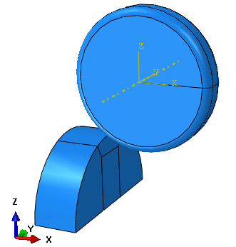
In the high speed cold roll-beating forming process, two rolling wheels with the same speed but reverse rotations facilitate the workpiece forming. This constitutes an axial symmetric problem. We therefore only considered half of the workpiece for our simulations. The geometric model is shown in Figure 1. The feed speed was chosen to be small, at 1 mm/s. In order to save computing time without affecting the accuracy of the simulation, only a segment of the workpiece was selected. The length and the radius of the workpiece were 12 mm and 20 mm, respectively, the rolling wheel radius was 19 mm, the tooth width was 8 mm, and the fillet radius was 2 mm.
The workpiece material model utilizes the Johnson–Cook constitutive equation. The material parameters of the constitutive equation are shown in Table 2.
Figure 1. The geometric model of cold roll-beating
Table 2. Material constants of the Johnson–Cook model of 40Cr
|
A/MPa |
B/MPa |
C |
m |
n |
Tr/K) |
ε0/s-1 |
Tm/K) |
|
905 |
226 |
0.03 |
0.83 |
0.21 |
20 |
0.004 |
1673 |
The rolling wheel material was Cr12MoV. In the high speed cold roll-beating forming process the rolling wheel only experienced elastic deformation, which is contrary to the case of 40Cr. It was regarded as a rigid body and was computationally modeled using an analytic rigid model, ignoring any elicited deformation.
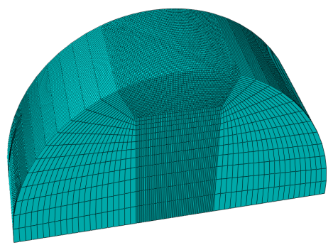
The rolling wheel struck the workpiece at a depth of 3 mm upon local contact. The mesh cell size at the contact area was 0.2 mm, and the others were set to 2 mm. Using a hexahedral structural unit, the meshing shown in Figure 2 was constructed with 165,960 cells. The cell types used for the high speed cold roll-beating thermal mechanical coupling and the finite element numerical simulations, without considering thermal effects, were C3D8RT and C3D8R. The rolling wheel was an analytic rigid model without meshing.
Figure 2. The computational mesh model of the workpiece
The freedom of movement of the rolling wheel was constrained along the x, y, z directions, and the freedom of rotational contrained along the x and z directions. The reference point in the x-y direction has the same coordinates as those of the rolling wheel’s center point, while the distance along the positive z direction is 36 mm offset from the rolling wheel’s center. At the reference point of the rigid model of the rolling wheel the loaded rolling wheel speed was set at 2000 rpm. Along the positive x direction the loaded feed rate was set to 1 mm/s on all nodes of the workpiece. The contact type was explicitly surface-to-surface , and the friction used a shear friction contact based on a penalty function formula, with the coefficient set to 0.2.
The total numerical simulation time for the high speed cold roll-beating thermal mechanical coupling was extremely short. The heat radiation between the workpiece and the environment, and heat radiation between the rolling wheel and the environment, the thermal exchange, and the contact heat between the rolling wheel and the workpiece, were all ignored. As the high speed cold roll-beating forming interrupted repeated striking, it led to longer periodes of non-contact between the rolling wheel and the workpiece than the periods of contact. The temperature of the rolling wheel touching the workpiece was not uniform, and cooling the workpiece should be considered. The heat transfer coefficient between the workpiece and the environment was 20 W/m2•K. It was not necessary to set thermal boundary conditions for the cold roll-beating numerical simulations.
3.2 Simulation assumptions
Three assumptions were asserted for the simulation as explained below.
(1) Heat effects: As the preliminary study of the thermalmechanical coupling of the cold roll-beating forming ignores any thermo-elastic effects associated with the forming process of the workpiece, the generated heat in the workpiece due to temperature changes can be expressed as follows:
$Q=\delta_{i j} \dot{\varepsilon}_{i j}^{p}-A_{k} \dot{V}_{k} .$ i.e. $\rho c \dot{T}=\delta_{i j} \dot{\varepsilon}_{i j}^{p}-A_{k} \dot{V}_{k}$ (3)
In the cold roll-beating forming process, not all dissipated energy of the workpiece is converted into heat energy . A small fraction of the dissipated energy is used for changes in the metal inside the microstructure (dislocation density, grain size, etc.). Therefore, the temperature variation of the workpiece can be expressed as:
$Q=\beta \delta_{i j} \varepsilon_{i j}^{p} .$ i.e. $\rho c \dot{T}=\beta \delta_{i j} \dot{\varepsilon}_{i j}^{p}$ (4)
Integrating equation (3) for the cold roll-beating forming process can result in an equation for the transient temperature changes of the workpiece per unit volume as follows:
$\rho c \Delta T=\beta \int \delta_{i j} \dot{\varepsilon}_{i j}^{p} d t \quad$ i.e $\Delta T=\frac{\beta}{\rho c} \int \delta_{i j} \varepsilon_{i j}^{p} d t$ (5)
(2) Contact friction: It is assumed that the friction coefficient during the process of the rolling wheel striking the workpiece is uniform.
(3) Workpiece material properties: It is assumed that the metal is incompressible and possesses initial isotropy.
3.3 Temperature analysis
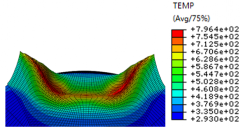
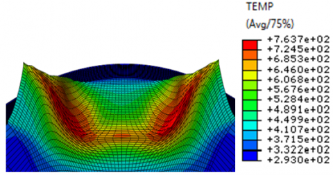
The temperature distribution of the workpiece at different instances is shown in Figure 3 for the high speed cold roll-beatling forming process. Figure 3 (a) represents the temperature distribution of the workpiece while the rolling wheel is in contact with it, Figure 3 (b)–(c) represent the temperature distribution in the workpiece during the process at which the rolling wheel strikes the workpiece. Figure 3 (d) shows the temperature distribution of the workpiece when the rolling wheel was immediately detached from the workpiece and after a hitting forming process was completed. As can be seen from Figure 3, the high temperature region produced in the parts of the workpiece contacted by the rolling wheel has an uneven temperature distribution. The main reason is the conversion relationship between the plastic work and heat. Parts with large equivalent plastic deformation produced more plastic work. Consequently, the plastic work was converted to heat, and the corresponding temperature was higher.
(a) t = 0.22501 ms
(b) t = 0.45001 ms
(c) t = 1.0125 ms
(d) t = 2.25 ms
Figure 3. Temperature distributions at different times
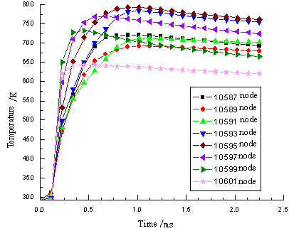
In order to further investigate the temperature change in each part of the workpiece in the whole cold roll-beating forming process, key nodes in the front section and on the side wall direction, those on the side of the workpiece in contact with the rolling wheel, were extracted as shown in Figure 4. Tracking analysis of the nodal temperatures, and the temperature temporal changes were extracted from the simulation results as shown in Figure 5.
Figure 4. Distribution of node locations
Tracking the temperature change of key nodes, can help determe trends in temperature change. For example, with the cold roll-beating forming process, the temperature of key nodes on each part of the workpiece experienced a sudden increase and a subsequent fall. However, the rising and falling slopes of key points in each workpiece part are different, with some nodes having a very large change in temperature. This is mainly attributed to the fact that the process of the rolling wheel striking the workpiece is not continuous. Tthe contact friction of the rolling wheel and the workpiece is converted to heat, and at the same time,the plastic deformation of the workpiece is also converted to heat,so the temperature of the workpiece increases. As the rolling wheel detaches from the workpiece, there is no longer plastic deformations or a rise in temperature. The workpiece temperature thus gradually decreases due to the heat exchange between the environment and the workpiece. Figures 5 shows that the temperature rise in nodes 10593 and 10595 is much higher, because in this part of the workpiece, the contact friction is severe, the deformation is violent, and heat dissipation is difficult.
Figure 5. Nodal temperature variations with time
3.4 Comparison and analysis of equivalent stress
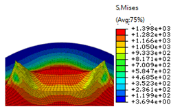
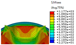
Figure 6 depicts the equivalent plastic strain distribution for a cold roll-beating forming process at different points in time, with and without consideration of thermal effects. Figures 6 (a) and (b) show the equivalent stress distributions of the roll-beating rounds at the moment of hitting the workpiece, without and with consideration of thermal effects respectively. Figures 6 (c) and (d) show the equivalent stress distributions when the cold roll-beating process is completed, at the moment when the roll-beating rounds detach from the workpiece, without and with considerations of the thermal effects respectively.
Figure 6 shows that the equivalent stress of the workpiece is larger in the case where thermal effects are not considered. There is a large noted difference in the equivalent stress distribution in the two cases, without and with thermal effects considered. When thermal effects are not considered, the maximum equivalent stress is observed mainly at the contact interface of the workpiece with the roll-beating wheel. In the case where thermal effects are considered, one of the areas where largest stress values are elicited is the contact location of the roll-beating round with the workpiece. This is mainly owing to the heat dissipation due to the plastic deformation resulting in increased mobility of the material. Thus, the cold roll-beating is more easily performed and the equivalent stress is decreased.
(a) t = 0.45001 ms without considering the thermal effect
(b) t = 0.45001 ms considering the thermal effect
(c) t = 2.25 ms without considering the thermal effect
(d) t = 2.25 ms considering the thermal effect
Figure 6. The equivalent stress distribution of the workpiece with and without consideration of thermal effects
Figure 7 depicts the unit comparison of the equivalent stress responses of the cold roll-beating forming with and without consideration of thermal effects, based on numerical simulations. Figure 8 shows the equivalent stress difference curves for specific cells (from Figure 4) of the cold roll-beating forming with and without consideration of the thermal effects, based on numerical simulations.
Figure 7. Unit comparison of equivalent stress response with and without consideration of thermal effects
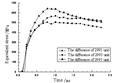
Figure 8. The equivalent stress difference curve for specific units, with and without consideration of the thermal effects
Based on such results, the stress of each unit has experienced a process of an abrupt rise and fall, andthe shape of the curves is similar. The elicited equivalent stress without consideration of the thermal effects is much larger compared to the case where thermal effects are considered. This is mainly because the plastic deformation work is converted into heat. The temperature rise leads to softening effects, and the unit of stress is reduced. Although the cold roll-beating numerical simulation uses the same material model irrespective of whether thermal effects were considered or not, the finite element software does not calculate the cold forming process of the temperature rise. The thermal softening part of the material constitutive equation becomes invalid, and the equivalent stress associated with the thermal effects is not accounted for. In this respect, the equivalent stress is much larger compared to the case where thermal effects are considered.
3.5 Comparison and analysis of equivalent strain
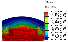
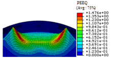
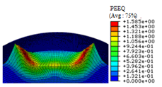
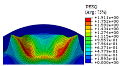
Figure 9 depicts the equivalent plastic strain variation of the high speed cold roll-beating based on numerical simulations, with and without consideration of the thermal effects. Figures 9 (a) and (b) represent the equivalent strain distribution of the roll-beating wheel striking the workpiece at the same time, without and with consideration of the thermal effects respectively. Figures 9 (c) and (d) show the equivalent strain distribution when a cold roll-beating process is completed, at the time of detachment of the roll-beating round from the workpiece, without and with consideration of the thermal effects respectively. The maximum plastic strain is generated when the roll-beating wheel is in direct contact with the workpiece. The maximum plastic strain in Figure 9 (b) is 1.585 which is greater than the corresponding maximum value of 1.476 shown in Figure 9 (a). The maximum plastic strain in Figure 9 (c) is 1.911 which is greater than the corresponding maximum value of 1.740 shown in Figure 9 (d). This is due to the rotational kinetic energy of the roll-beating wheel that is partially converted into plastic deformational energy of the workpiece, and partially converted into elastic energy. Therefore, most thermal–mechanical coupling effects lead to transformations of the plastic deformation energy into heat, which leads to new dramatic motion inside the metal. Thus the dislocation density and the deformation resistance of the metal are reduced, and the metal plastic deformation increases.
(a) t = 0.45001 ms without considering the thermal effect
(b) t = 0.45001 ms considering the thermal effect
(c) t = 2.25 ms without considering the thermal effect
(d) t = 2.25 ms considering the thermal effect
Figure 9. The equivalent strain distribution with and without consideration of the thermal effects
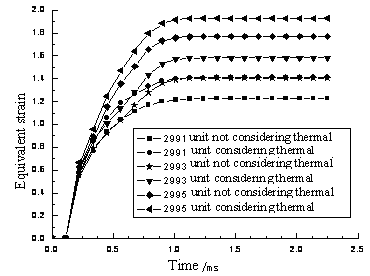
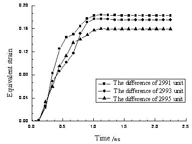
Figure 10 shows the equivalent plastic strain that was generated by the numerical simulation in the same unit, with and without consideration of thermal effects. Figure 11 shows the equivalent strain difference value produced by the numerical simulation of the cold roll-beating forming for the same equivalent stress, with and without consideration of thermal effects. It can be seen in Figures 10 and 11 that in the same, the equivalent unit plastic strain upon consideration of thermal effects is large. This is due to the size of the equivalent plastic strain that is influenced by deformation temperature and the rate and degree of deformation. Thus, the thermal effects resulting from the thermal–mechanical coupling effect cause the temperature of the workpiece and the equivalent plastic strain to both increase.
Figure 10. The contrast curve of equivalent plastic strain with and without consideration of thermal effects
Figure 11. The contrast curve of equivalent strain difference with and without consideration of the thermal effects
The deformation of 40Cr quenched and tempered steel at high strain rates is an adiabatic process, where the temperature is a function of strain. The adiabatic temperature rise of plastic deformation under high strain rates is expressed by the following equation:
$\Delta T=\frac{\beta}{\rho C_{p}} \int_{0}^{\varepsilon^{p}} \sigma\left(\varepsilon^{p}\right) d \varepsilon^{p}$ (6)
Where, $\rho$ is the material density, ρ=7.87 kg/m3, and $C_{p}$ is the specific heat capacity, and equals to 470 J/(kg•k)
Integrating the Johnson–Cook constitutive equation (2) into equation (6), the adiabatic temperature rise produced under a high strain rate with the Johnson–Cook constitutive equations becomes:
$\Delta T=\frac{\beta}{\rho C_{p}} \int_{0}^{\varepsilon^{p}} \sigma\left(\varepsilon^{p}\right) d \varepsilon^{p}=\frac{\beta \varepsilon^{p}}{\rho C_{p}}\left[A+\frac{B}{n+1}\left(\varepsilon^{p}\right)^{n+1}\right]\left[1+C \ln (\dot{\varepsilon})^{*}\right]\left[1-\left(T^{*}\right)^{m}\right]$ (7)
Substituting into equation (7) the parameters which correspond to the unit conversion after their acquisition results in the following equation:
$\Delta T=\frac{0.9 \varepsilon^{p}}{0.787 \times 4.7}\left[905+\frac{226}{0.26+1}\left(\varepsilon^{p}\right)^{0.26+1}\right]$
$\left[1+0.03 \ln (\dot{\varepsilon})^{*}\right]\left[1-\left(T^{*}\right)^{0.83}\right]$ (8)
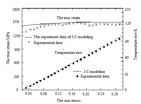
Figure 12 shows the comparison of the true strain based on the Johnson–Cook model with data from the experiment. Additionally, shown in the same figure is a comparison of the experimental data of the temperature rise and the calculated temperature rise data based on the Johnson–Cook model, under the condition of the contrasting strain rate of 2534s-1, and at a normal temperature. As can be seen in sthe figure, there is consistency between the true stress from the Johnson–Cook model and the experimental data. There is also consistency between the estimated temperature rise based on the Johnson–Cook model and the calculated value based on the experimental data. In association, findings provide the theoretical basis and the material parameters for additional finite element simulations using thermal–mechanical coupling.
Figure 12. The 40Cr experiments and the forecasted results (2534 s-1 strain rate and at room temperature)
Figure 13 is a comparison of the predicted flow stress based on the Johnson–Cook constitutive equation with experimental data, at different temperatures. It can be seen in this figure, for a strain rate value of approximately 1000 s-1, and as the temperature rises, the flow stress due to the thermal softening effect is decreased. This indicates that the predictions of the Johnson–Cook model agree with real experimental data at different temperatures. This indicates that the dynamic constitutive model presented in this paper can effectively predict the plastic flow stress of 40Cr quenched and tempered steel at different temperatures.
Figure 13. Comparison of forecasted with experimental flow stress for 40Cr at different temperatures
In the cold roll-beating forming process, the produced thermal effect affects the metal flow in the workpiece forming process and eventually has an impact on the quality and performance of the molded parts. It is therefore necessary to study the forming mechanism of the cold roll-beating forming process under thermal–mechanical coupling conditions.
(1) In this paper, through the Hopkinson pressure bars system, a set of 40Cr true stress-strain curves for different temperatures is obtained. Using least squares curve fitting, the Johnson–Cook dynamic constitutive equations for 40Cr have been identified based on experiments. (2) An ABAQUS simulation model was established for 40Cr based on the Johnson–Cook dynamic constitutive equations, and the thermal effects on the process of forming a workpiece with 40Cr quenched and tempered steel cold roll-beating were simulated. (3) Based on the comparisons of experimental and calculated data for the Johnson–Cook constitutive equations, it is concluded that the dynamic constitutive model presented in this paper can provide a theoretical basis for thermal mechanical coupling research questions in the forming process of 40Cr high-speed cold roll-beating.
The dynamic constitutive model presented in this paper can effectively predict plastic flow stress for 40Cr quenched and tempered steel under different temperatures, and the research can provide the theoretical basis for the further assessment of the thermal mechanical coupling effects of 40Cr high-speed cold roll-beating forming process.
This project is supported by the National Natural Science Foundation of China [Grant No. 51475366, 51475146], the Specialized Research Fund for the Doctoral Program of Higher Education of China [Grant No. 20116118110005], the Key Laboratory of Scientific Research Projects of Shaan'xi Educational Committee [Grant No. 12JS072] and the Research Fund for the Doctoral Innovation Program of Xi'an University of Techonlogy [Grant No. 207-002j1302].
1. H. Yang, X. G. Fan, Z. C. Sun, L. G. Guo and M. Zhan, Some Advances in Local Loading Precision Forming of Large Scale Integral Complex Components Of Titanium Alloys, Materials Research Innovations, vol 15(s1), pp, 493-S498,2011. DOI: 10.1179/143307511X12858957676119.
2. R. Neugebauera, K.-D. Bouzakisb and B. Denkenac, Velocity Effects in Metal Forming and Machining Processes, CIRP Annals-Manufacturing Technology, vol. 60(2), pp. 627-650, 2011. DOI: 10.1016/j.cirp.2011.05.001.
3. M. Merkleina, J. M. Allwoodb and B. A. Behrensc, Bulk Forming of Sheet Metal, CIRP Annals-Manufacturing Technology, vol. 61(2), pp. 725-745, 2012. DOI: 10.1016/j.cirp.2012.05.007.
4. F. K. Cui, W. J. Zhu, X. Q. Wang and F. S. Zhang, Current Research and Development Trends of High Speed Cold Rolling Technology, Journal of Henan Polytechnic University, vol. 31(2), pp. 191-195, 2012.
5. L. Zhang, Y. Li, M. S. Yang and F, K, Cui, Recent Development of Incremental Forming, Aerospace Materials & Technology, vol. 06, pp. 32-38, 2011.
6. H. Krapfenbauer, New Aspects for the Mass Production of Spur Gears by Cold Rolling, IPE International Industrial & Production Engineering, vol. 8(3), pp. 39- 41, 1984.
7. H. Krapfenbauer, New methods to Cold Roll Splines on Hollow Blanks, European Production Engineering, vol. 1(9), pp. 39-43, 1994.
8. J. H. Quan, F. K. Cui and J. X. Yang, Numerical Simulation of Involute Spline Shaft’s Cold-rolling Forming Based on ANSYS/LS-DYNA, China Mechanical Engineering, vol. 19(4), pp. 419-422, 2008.
9. L. Zhang Lu, Y. Li and M. S. Yang, Study on Metal Flowing of Lead Screw Cold Roll-beating Forming, China Mechanical Engineering, vol. 23(13), pp. 1623- 1628, 2012.
10. M. S. Yang, Y. Li and Q. L. Yuan. A Hybrid Method to Deformation Force of High-speed Cold Roll-beating Forming, Journal of Digital Information Management, vol. 11(2), pp. 146-153, 2013.
11. Q. L. Yuan, Y. Li, M. S. Yang and Y. X. Li Yuxi, Research on Deforming Force of Slab Cold Roll-beating, China Mechanical Engineering, vol. 25(2), pp. 251-256, 2014.
12. P. Hakansson, M. Wallin and M. Ristinmaa, Comparison of Isotropic Hardening and Kinematic Hardening in Thermoplasticity, International Journal of Plasticity, vol. 21(7), pp. 1435-1460, 2005. DOI: 10.1016/j.ijplas.2004.07.002.
13. P. LONGERE and A. DRAGON, Evaluation of the Inelastic Heat Fraction in the Context of Microstructure- Supported Dynamic Plasticity Modeling, International Journal of Impact Engineering, vol. 35(9), pp. 992-999, 2008. DOI: 10.1016/j.ijimpeng.2007.06.006.
14. Z. Y. Jiang, A. K. Tieu And C. Lu, Three-dimensional Thermo-Mechanical Finite Element Simulation of Ribbed Strip Rolling with Friction Variation, Finite Elements in Analysis and Design, vol. 40(9-10), pp. 1139-1155, 2004. DOI: 10.1016/j.finel.2003.08.004.
15. H. Li, M. Zhan, and H. Yang He, Coupled Thermal- Mechanical FEM Analysis of Power Spinning of Titanium Alloy Thin-walled Shell, Chinese Journal of Mechanical Engineering, vol. 44(6), pp. 187-193, 2008. DOI: 10.3901/JME.2008.06.187.
16. Y. C. Lin, X. Chen and G. Liu, A Modified Johnson- Cook Model for Tensile Behaviors of Typical High- Strength Alloy Steel, Materials Science and Engineering: A, vol. 527(26), pp. 6980-6986, 2010. DOI: 10.1016/j.msea.2010.07.061.
17. D. Samantaray, S. Mandaland, A. K. Bhaduri., A Comparative Study on Johnson Cook, Modified Zerilli- Armstrong and Arrhenius-Type Constitutive Models to Predict Elevated Temperature Flow Behaviour in Modified 9Cr-1Mo Steel, Computational Materials Science, vol. 47(2), pp. 568-576, 2009. DOI: 10.1016/j.commatsci.2009.09.025.