Nicolò Morselli | Marco Puglia | Simone Pedrazzi* | Paolo Tartarini | Giulio Allesina
© 2021 IIETA. This article is published by IIETA and is licensed under the CC BY 4.0 license (http://creativecommons.org/licenses/by/4.0/).
OPEN ACCESS
Among the renewable sources, residual woody biomass from agricultural crops is becoming of great interest due to its lower environmental impact and one of the most growing agricultural sector, of the last decade, is the hemp industry which generates several kind of byproducts. In this paper, a blend of 50% of hemp-hurd and 50% of fir sawdust was pulverized and pelletized. The pellets were burned into a domestic pellet stove (9 kWth maximum nominal thermal power output) at different biomass flowrates. To compare results with a commercial-grade pellet, the tests were repeated by fueling the same stove with A2-grade pellets.
Results shown that the pellet mixture 50/50 of fir sawdust and hemp-hurd is suitable for the commercial pellet stove used and that the slightly higher amount of ashes (2.7%), compared to pellet A2 (<1.2%), can be handled by the self-cleaning fire chamber. Comparable results were also obtained in regards with the stove global efficiency which ranged from 90.8-92.3% for the hemp pellets and 91-94% for the A2. A significant difference was noted in the biomass flowrate where, during the tests with hemp-hurd pellets a lower value was obtained (-20%) compared to A2. This resulted into lower power input in the stove and lower performances at the same nominal power output.
hemp-hurd, pellet, stove, combustion, efficiency
One of the most diffused byproducts of the hemp industry is the hemp hurd which, for some varieties of hemp plant, can represent up to the 70% of the raw material [1]. Hemp hurd can be considered woody biomass since it is mainly composed of lignin (17-19%), hemicellulose (21-25%) and cellulose (34-48%) [2] and it is therefore interesting for thermochemical conversion processes. One of the most common thermochemical path to convert residual biomasses is gasification [3-8], while, few references are related to the combustion of residual byproducts in domestic stoves.
In this work was then chose to test the combustion of hemp-hurd derived pellet into a commercial pellet stove capable of 9 kWth of thermal power output. The stove has an automated feeding system, an air/fumes heat exchanger, and a control system able to regulate the thermal power output to a fixed value or in order to maintain a desired room temperature.
For this paper, three different thermal power output (5, 7 and 9 kWth) were tested to assess the heat exchanger effectiveness and global efficiency of the stove under different fuels. For this purpose, hemp-hurd pellets fuel was compared to A2-grade commercial pellet.
Since the hemp-hurd is difficult to pelletize [1, 2], it was choosing to mix it with a 50%wt of fir sawdust. The 50/50 blend was then pulverized, pelletized and an elemental/ashes analysis was carried out.
Results shows that the pellet mixture 50/50 of fir sawdust and hemp-hurd is suitable for the commercial pellet stove used. In-fact, the hemp-hurd pellets ashes (2.7%) are slightly higher compared to pellet A2 ashes (<1.2%), therefore hemp-hurd pellets ashes can be handled by the self-cleaning fire chamber of the stove. The heat exchanger effectiveness and stove global efficiency shown comparable results. Stove global efficiency ranged from 90.8-92.3% using hemp pellets and 91-94% using A2. Instead, a significant difference was noted in the biomass flowrate: during the tests with hemp-hurd pellets a lower value was obtained (-20%) compared to A2.
2.1 Hemp-hurd pelletization
The hemp-hurd is generally found in the form of sticks/chunks (Figure 1), due to the shredding process that the hemp faces in the harvesting procedure.
Figure 1. Hemp-hurd chunks as received from the producer
This form factor is not suitable for most of the domestic stoves which are fueled with wood logs or pellets. For this reason, the hemp residues needed to be pelletized to homogenize the form factor and make them suitable for the selected stove. Literature reports studies regarding the palletization of agricultural residues for energy purposes (i.e., palm fruit skins [9], vine pruning [5], digestate [10]).
As reported in the paper from Pedrazzi et al. [11], the palletization of hemp-hurd is challenging due to its structure composition and a certain amount of fir sawdust need to be added to obtain a stable and compact pellet.
In this work, the hemp-hurd chunks were firstly pulverized by means of an electric grinder and then mixed with a 50% of fir sawdust. A domestic-scale electric pelletizer was used to compress the biomass mix into pellets 6 mm diameter.
2.2 Pellet stove instrumentation
To test the capability of hemp-hurd to be a reliable fuel for domestic heating, a commercial pellet stove with a nominal power of 9 kWth was used as a test rig. The selected stove use forced air flow to dissipate the combustion heat and no hydronic devices are present. The stove can be subdivided into 4 main blocks (Figure 3a):
In the paragraphs below, the test rig setup is shown together with the instrument used to carry out energy and efficiency calculations.
2.2.1 Air flowrate measurements
Three different flows need to be considered to take into account the energy pathways of the stove (Figure 3a): the air flowrate of the air blower for exhaust gas cooling (A), the flowrate of the blower for the combustion air (B) and the flowrate of the biomass (C).
The cooling air flowrate was measured by means of a fan anemometer (TESTO 417) which was adapted to the stove by building a plenum between the fan inlet and the instrument itself. The second measurement is the airflow necessary for the combustion and, in this case, a volumetric meter was connected to the inlet hose of the fire chamber. The exhaust flowrate was then calculated according to the equations reported in the paragraph 2.3.4.
2.2.2 Temperature measurements
A thermocouple datalogger TC-08 from PicoTech was used to log the temperatures at strategic locations in the stove.
In the Table 1 below, a scheme of the thermocouple used is reported. The same nomenclature is also used in the results chapter and the progressive numbers are reported in Figure 3b, c, d showing the position of the probes on the stove.
Table 1. Thermocouples installation scheme
|
# |
Location |
TC type |
Accuracy [℃] |
|
1 |
Ambient |
T |
± 1 |
|
2 |
Heat exchanger left top (HX L TOP) |
T |
± 1 |
|
3 |
Heat exchanger right top (HX R TOP) |
T |
± 1 |
|
4 |
Heat exchanger left bottom (HX L BOT) |
T |
± 1 |
|
5 |
Heat exchanger center bottom (HX C BOT) |
T |
± 1 |
|
6 |
Heat exchanger right bottom (HX L TOP) |
T |
± 1 |
|
7 |
Flame |
K |
± 2 |
|
8 |
Exhaust |
K |
± 2 |
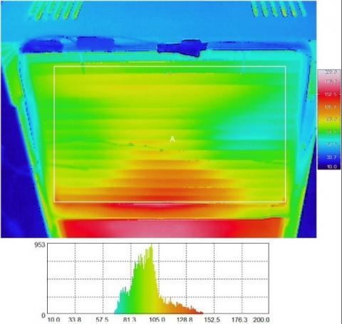
As shown in the thermal image in Figure 2, the temperature distribution at the heat exchanger outlet on the room side is far from be homogeneous. For this reason, 5 thermocouples were placed at the HX outlet to average the result.
Figure 2. Thermal image of the heat exchanger outlet which shows the temperature inhomogeneity at the heat exchanger outlet
Figure 3. Scheme (a) and instrumentation of the wood pellet stove (b, c, d)
2.3 Test methodology
2.3.1 Pellet chemical characterization
Pellet characterization follows several steps in order to obtain all the information needed to assess the heating value of the biomass. The moisture content of the pelletized material was measured according to the ASTM E1756-08 standard method (Eq. (1)) both for the hemp-hurd and for the A2 grade commercial pellet.
$M_{B I O, W B}=\frac{m_{B I O, w e t}-m_{B I O, d r y}}{m_{B I O, w e t}}$ (1)
The chemical composition of the different pellets was characterized through the ultimate analysis, performed with a CHNS-O analyzer, that returns the weigh fraction of carbon, hydrogen, nitrogen, sulfur and oxygen. The ash content was determined through a 6 hours muffle furnace calcination at 600℃. The chemical and moisture analyses were used to calculate the biomass higher heating value according to the Channiwala-Parikh correlation [12] (Eq. (2)).
$\mathrm{HHV}_{\mathrm{BIO}}=349.1 \mathrm{C}+1178.3 \mathrm{H}+100.5 \mathrm{~S}-103.40$
$-15.1 \mathrm{~N}-21.1 \mathrm{ASH}$ (2)
The chemical analysis was then repeated on the combustion residues collected from the ash vessel at the end of each test and the composition and ash content of these residues was used to accurately calculate the amount biomass that was really burned during the test. This data is necessary to calculate the amount of exhaust gases flowrate starting from the measurement of the inlet airflow for combustion. The followed procedure is shown in the paragraph 2.3.3.
2.3.2 Combustion test procedure
The combustion tests were carried out with the stove installed inside a room. The room (ambient) temperature was kept constant during the tests by mixing the room air with the colder external one.
To compare the performance of hemp-hurd derived pellets versus A2 standard pellet, three tests were carried out for each class at three different stove nominal power output: 5, 7 and 9 kWth which correspond to three different feeding auger speed (5, 7 and 9).
The stove power is selected via ECU digital panel and at each power output the stove regulates the speed of the feeding auger to match the power needed, according to the pellet heating value manually entered in the ECU. Since there is no loop control on what the actual power of the stove is, an ex-post calculation based on the collected data was carried out and presented in the equations below. The testing procedure is resumed in the following steps:
2.3.3 Biomass flow rate calculation at steady state
During each test the pellet stove passes through several steps from startup to shut down:
The biomass consumption calculation, for the purpose of estimating the chemical power, need to be carried out at steady state, while the stove is at the prefixed power output. For this reason, the ignition load and the biomass consumption in the ramp up period need to be removed from the total.
While the ignition load can be measured by stopping the stove after the initial load phase and weighing the biomass contained by the fire chamber, the ramp up biomass load can only be indirectly calculated from the equations below by knowing the total biomass consumption and the time spent at each power step. The apex ( ' ) indicates nominal results based on the stove setup parameters.
$E_{B I O, t o t}^{\prime}=\sum_{i=2}^{\text {steady }} \dot{P}_{B I O, i}^{\prime} \cdot \Delta t_{i}$ [J] (3)
$E_{\text {BIO,steady }}^{\prime}=\dot{P^{\prime}}_{\text {BIO,steady }}^{\prime} \cdot \Delta t_{\text {steady }}$ [J] (4)
$\begin{aligned} m_{\text {BIO,steady }} &=\frac{E_{\text {BIO,steady }}^{\prime}}{E_{\text {BIO,tot }}^{\prime}} \cdot\left(m_{\text {bio,tot }}\right.\\ &\left.-m_{\text {bio,ign }}\right) \end{aligned}$ [kg] (5)
Hence, the biomass flowrate at steady state condition can be calculated as follows:
$\dot{m}_{B I O}=\dot{m}_{B I O, \text { steady }}=\frac{m_{\text {BIO,steady }}}{\Delta t_{\text {steady }}} \quad\left[\operatorname{kg} h^{-1}\right]$ $\left[\mathrm{kg} h^{-1}\right]$ (6)
According to the biomass HHV the real power output was calculated according to the next equation:
$\dot{P}_{B I O}=\dot{P}_{B I O, \text { steady }}=\dot{m}_{B I O} \cdot H H V_{B I O}$ [W] (7)
2.3.4 Exhaust gases flowrate estimation
The fumes flowrate estimation is based on two information:
The flowrate of each element composing the biomass was calculated according to the biomass flowrate at steady state conditions and the mass concentration of the element X.
$\dot{m}_{X, B I O}=\dot{m}_{B I O} \cdot X_{\%} \quad\left[\operatorname{kg} h^{-1}\right]$ (8)
The same element may remain in the combustion residues, and contributes to the residues flowrate:
$\dot{m}_{X, R E S}=\dot{m}_{B I O} \cdot X_{A S H, \%} \cdot \frac{A S H_{B I O, \%}}{A S H_{R E S . \%}} \quad\left[\mathrm{~kg} h^{-1}\right]$ (9)
The combustion products were calculated according to the net mass flow of elements that participated to the combustion:
$\dot{m}_{C O_{2}}=\frac{\dot{m}_{C, B I O}-\dot{m}_{C, R E S}}{12} \cdot 44 \quad\left[\mathrm{~kg} h^{-1}\right]$ (10)
$\dot{m}_{H_{2} O}=\frac{\dot{m}_{H_{2} O, B I O}-\dot{m}_{H_{2} O, R E S}}{2} \cdot 18 \quad\left[\mathrm{~kg} h^{-1}\right]$ (11)
The combustion of biomass is usually performed with an excess of air (thus of oxygen) [13] to guarantee a complete burning of the solid material. The calculation of the residual oxygen in the exhaust gases can be obtained by adding the oxygen in the combustion air to the one present in the molecular structure of the biomass and removing the oxygen present in the combustion residues.
$\dot{m}_{O_{2}}=\dot{m}_{O_{2}, A I R}+\dot{m}_{O_{2}, B I O}-\dot{m}_{O_{2}, R E S}$$-\dot{m}_{O_{2}, \text { stoichio }}$ $\left[\mathrm{kg} h^{-1}\right]$ (12)
where,
$\dot{m}_{O_{2}, \text { stoichio }}=\frac{\dot{m}_{C, B I O}-\dot{m}_{C, R E S}}{12} \cdot 32+\frac{\dot{m}_{H, B I O}-\dot{m}_{H, R E S}}{2} \cdot 16 \quad\left[\mathrm{~kg} h^{-1}\right]$ (13)
is the oxygen needed for the stoichiometric combustion of the net biomass flowrate. According to these equations it is possible to define the excess air (e) as in the following:
$e=\frac{\dot{m}_{O_{2}, A I R}}{\dot{m}_{O_{2}, \text { stoichio }}}$ (14)
In Figure 4 a Sankey diagram resumes the biomass and air pathways explained in the above equations.
Figure 4. Example of the combustion pathways for standard A2 pellet
The exhaust gas flowrate is then calculated as follows:
$\dot{V}_{E X}=\sum_{i}^{N} i_{\%} \cdot \dot{m}_{b i o} \quad\left[\operatorname{kg} h^{-1}\right]$ (15)
where, i stays for the mass fraction of each component of the exhaust: N2, Ar, H2O, CO2 and O2.
2.3.5 Energy calculation
The heat generated during the combustion is dissipated in several ways: during the startup period, part of the heat is stored as sensible heat in stove structure while the remaining part is dissipated through natural convection and radiation from the hot surfaces of the device, forced convection through the air/fumes HX and part of it is lost at the chimney.
Since the calculation of the convective heat transfer coefficient can be affected by a significant uncertainty, in this paper, the evaluation and comparison of the wood stove efficiency between the different fuels was carried out by comparing:
The former was calculated according to Eq. (16) which represent the energy balance between the heat exchanger inlet and outlet.
$\dot{Q}_{H X}=\dot{V}_{A I R, H X} \cdot \rho_{A I R} \cdot c_{p, A I R} \cdot\left(T_{A m b i e n t}-\bar{T}_{H X}\right)[W]$ (16)
The latter was calculated in the same way but using the calculated exhaust flowrate (Eq. (17)).
$\dot{Q}_{E X H A U S T}=\dot{V}_{E X} \cdot \rho_{E X} \cdot c_{p, E X} \cdot\left(T_{E x h a u s t}-T_{A m b i e n t}\right) \quad[W]$ (17)
Where the density ($\left(\rho_{A I R}\right)$) and the specific heat capacity $\left(c_{p, A I R}\right)$ were calculated referring to the ambient temperature of the air through the following equations extrapolated from Eq. (16):
$\rho_{A I R}=-2.673748 \cdot 10^{-14} \cdot T^{5}+4.77340 \cdot 10^{-12} \cdot T^{4}-3.56265 \cdot 10^{-8} \cdot T^{3}+1.53559$
$\cdot 10^{-5} \cdot T^{2}-4.75260 \cdot 10^{-3} \cdot T+1.3$ (18)
$c_{p, A I R}=-2.64444 \cdot 10^{-8} \cdot T^{3}+6.81522 \cdot 10^{-5} \cdot T^{2}+1.40874 \cdot 10^{-1} \cdot T+951.71757$ (19)
and the same properties for flue gases were calculated referring to similar equations, extrapolated from [14], but modified according to the calculated flue gas composition.
2.3.6 Effectiveness and efficiency parameters
According to the above heat power output definitions, two key parameters can be identified to facilitate the comparison between hemp-hurd derived pellets and standard A2 pellets.
The effectiveness of the forced convection heat exchanger:
$\eta_{F C}=\frac{\dot{Q}_{F C}}{\dot{P}_{B I O}}$ (20)
and the overall efficiency of the pellet stove:
$\eta_{t o t}=1-\frac{\dot{Q}_{E x h a u s t}}{\dot{P}_{B I O}}$ (21)
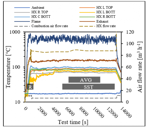
The effectiveness and efficiency calculation were based on the data collected at the steady state regime of the stove, i.e., when temperatures and flowrate can be considered constant. To achieve this condition, the stove passes through a series of increasing power steps until the setpoint power is reached. From the observations during the tests, the stove can be considered at steady state condition after 1.5 hrs from the end of the ramp-up period and to make the calculation shown above, all the data were averaged on a period of at least 2 hrs at steady state.
Figure 5. Temperature and flowrate trends during the test with A2 grade pellet. Ramp-up (R), steady state (SST) and data averaging (AVG) period are shown.
The graph in Figure 5 shows the position of these time periods over a run.
3.1 Pellet and combustion residues characterization
3.1.1 Pellet geometrical comparison
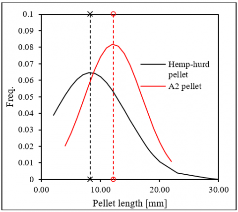
A geometrical comparison was carried out between the two selected fuels in order to investigate the dimensional variability. The following graph (Figure 6) represents the pellet length distribution measured over a sample of 100 g for each type.
Figure 6. Distribution of the pellet length over a sample of 100 g. The dashed lines represent the average value for each type
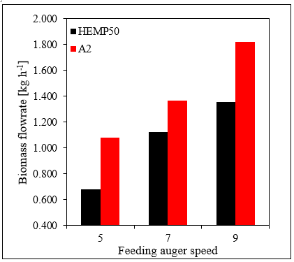
Despite the mixing with a 50% of fir sawdust, the hemp-hurd pelletization process tends to generate shorter pellets, if compared to A2, and it is more prone to generate dust and oversized pellets (>25 mm). These analyses warn also on the possibility that the feeding auger could response in a different way from A2 to hemp-hurd pellet: the oversized pellet tend to lower the filling rate of the auger and lower the real biomass flowrate at the same power setpoint, as shown in Figure 7.
Figure 7. Calculated biomass flowrate at the same auger speeds and at steady state conditions
3.1.2 Ultimate and ash content analyses
Table 2 resumes the results of the pellets ultimate analyses and ash content. The elemental analysis and ash content are calculated on a dry-basis biomass sample, while the moisture content is measured on an as-received sample. For the A2 grade commercial pellets was not possible to test the ash content and the reported value is declared by the producer.
Table 2. Pellet samples ultimate analysis, ash and moisture content, and calculated HHV
|
Pellet type |
C [%] |
H [%] |
N [%] |
S [%] |
O [%] |
ASH [%] |
MWB [%] |
HHV [MJ kg-1] |
|
A2 |
49.4 |
6.0 |
0.0 |
0.0 |
43.4 |
<1.2 |
6.7 |
>19.8 |
|
HEMP50 |
46.1 |
6.4 |
0.0 |
0.0 |
48.0 |
2.65 |
11.9 |
18.9 |
The combustion residues of the tests with A2 and hemp-hurd derived pellet at the feeding auger speed 7 were analyzed to detect the effectiveness of the combustion process and results are shown in the Table 3 below.
Table 3. Combustion residues ultimate analysis and ash content
|
Pellet type |
C [%] |
H [%] |
N [%] |
S [%] |
ASH + O [%] |
|
A2 residues |
3.15 |
0.38 |
0.0 |
0.0 |
96.47 |
|
HEMP50 residues |
3.76 |
0.45 |
0.0 |
0.0 |
95.79 |
3.2 Performance comparison
The pellet stove performance comparison between the different fuels at different thermal power output were based on the calculation of the effectiveness of the heat transfer in the forced convection heat exchanger (ηFC) and the total efficiency of the stove (ηtot).
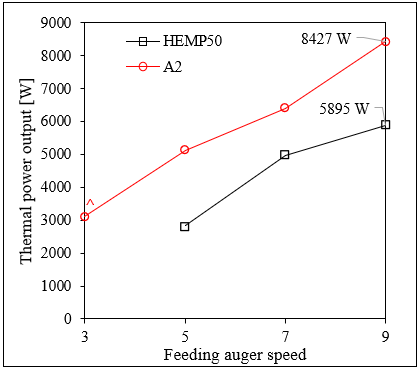
Tests were carried out at 3 different biomass flowrates (i.e. at 3 different nominal thermal power outputs) and results, in terms of thermal power output, are shown in the graph of Figure 8 according to the feeding auger speed.
It can be noted that the maximum thermal power output reached by the hemp-hurd pellet was 5.9 kWth at the maximum speed of the feeding auger (9), while, for the A2 pellet was 8.4 kWth. On the other hand, it is shown how for the A2 pellet was necessary to add an extra test (^ in Figure 8) at a lower auger speed (3) in order to be able to match the results with the test at speed 5 carried out with hemp-hurd pellets.
Figure 8. Thermal power output of the stove at different feeding auger speed. Maximum power output is reported on the right side of each line
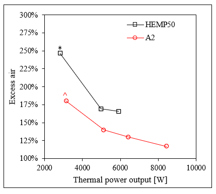
The overall efficiency of the stove generally tends to decrease while the thermal power output increase (Figure 9) when the stove is fueled with A2 pellets. In the combustion tests with HEMP50 pellets it was noticed and efficiency peak at intermediate (7) auger speed rate. This behavior was due to the different stove setup which automatically regulates the combustion air flow rate. In fact, the test (*) in Figure 9 shows higher heat exchanger effectiveness and lower overall efficiency because the heat exchanger fan was operating at higher speed than the test (^) resulting in higher portion of heat removed via forced convection. On the other hand, the combustion air flow rate at (*) was higher than (^), as confirmed by the excess air in Figure 10, increasing the heat lost at the chimney and decreasing the overall efficiency.
In Figure 10 the excess air is reported, and it can be noted that the stove setup is not optimized for hemp pellet which results in excess air up to 236%. This is mainly due to the constructor setup of the combustion blower which regulates its speed according to the nominal power output set by the ECU.
Figure 9. Effectiveness (ηFC) of the heat exchanger and total efficiency of the stove (ηtot) at different thermal power output
Figure 10. Excess air at different stove thermal power output
In this work, the capability of hemp-hurd derived pellet to be used as fuel in domestic pellet stove was investigated and compared to standard A2-grade commercial pellet. To increase the pelletability of hemp hurd, a 50% of fir sawdust was added to the hemp chunks and, this mixture, gave the chance to form pellet on average shorter than the commercial ones but with a higher variability. In fact, the average dimension of A2 pellets was 12.2 mm while for the hemp-hurd ones was 8.2 mm. The variability of the dimensions was 4.9 mm for the A2 and 6.2 mm for the hemp pellets which shown pellets even longer than 30 mm that resulted in a lower filling rate of the auger and thus a lower biomass input flowrate if compared to A2.
The ultimate and ash analyses of the fuels shown a very similar composition resulting in an HHV of 19.8 MJ kg-1 for the A2 and 18.9 MJ kg-1 for the hemp pellet. Even if the ash content of the hemp pellets resulted in 2.7%, the grate cleaning mechanism of the stove was able to self-clean the fire chamber keeping the performances constant over the test.
The performance comparison was carried out by testing the fuels combustion at different thermal power output, involving the calculation of the overall stove efficiency and the effectiveness of the air/fumes heat exchanger. Results shown an overall efficiency always over 90% for both the fuels, with a slight advantage for A2 pellet, likely due to the higher flame temperatures which resulted also in a higher heat exchanger effectiveness.
The excess air was noticed to be not aligned with the hemp-hurd pellet combustion, giving values up to 236 %, compared to the 140% of the A2 at the same stove setup. This is mainly due by the fact that there is no feedback loop control con the combustion air flow rate based on the excess air (no oxygen sensor available in this stove model) and it can affect the pollutant emission of the stove. For this reason, further tests should be carried out to investigate the optimal parameters for the hemp fuel.
Concluding, the 50/50 mixture between fir sawdust and hemp-hurd chunks can be considered a pelletizable fuel for domestic pellet stove. Attention should be paid in both investigating the pelletization process, in order to homogenize the pellet dimensions, and to modify the wood stove parameters in order to increase the auger feeding rate and thus to reach the maximum nominal power of 9 kWth even running under hemp-hurd.
This work was funded by the Italian MIUR project UNIHEMP – Utilizzo di Biomassa da Canapa Industriale per la produzione di energia e nuovi biochemicals (cod. ars01_00668).
|
M |
Moisture content of the biomass |
|
m |
Mass, kg |
|
HHV |
Higher heating value, J kg-1 ℃-1 |
|
C |
Carbon content, % |
|
H |
Hydrogen content, % |
|
S |
Sulfur content, % |
|
O |
Oxygen content, % |
|
N |
Nitrogen content, % |
|
Ar |
Argon content, % |
|
ASH |
Ash content, % |
|
X |
Generic chemical element |
|
E’ |
Nominal energy, J |
|
$\dot{Q}$ |
Thermal power output, W |
|
$\dot{V}$ |
Volumetric flowrate, m3 h-1 |
|
$\dot{P}$ |
Chemical power, W |
|
$\rho$ |
Density, kg m-3 |
|
$c_{p}$ |
Specific heat capacity, J kg-1 ℃-1 |
|
T |
Temperature, ℃ |
|
Nm3 |
Normal cubic meter, measured at 0℃ and 1.0325 bar |
|
Greek symbols |
|
|
η |
Efficiency |
|
ε |
Effectiveness |
|
Δ |
Difference between two different points at steady state conditions |
|
Subscripts |
|
|
BIO |
Referred to the biomass |
|
RES |
Referred to combustion residues |
|
FC |
Forced convection |
|
dry |
Referred to a dry sample |
|
wet |
Referred to a moist sample |
|
% |
Percentage value |
|
ign |
Ignition phase |
|
steady |
Steady-state phase |
|
stoichio |
Referred to stoichiometric combustion |
|
WB |
Wet basis |
|
X |
Referred to the x-th chemical element |
|
EX |
Value referred to the exhaust gases |
|
HX |
Value referred to the heat exchanger |
|
p |
Constant pressure |
[1] Karus, M., Vogt, D. (2004). European hemp industry: cultivation, processing and product lines. Euphytica, 140(1-2): 7-12. https://doi.org/10.1007/s10681-004-4810-7
[2] Salami, A., Raninen, K., Heikkinen, J., Tomppo, L., Vilppo, T., Selenius, M., Raatikainen, O., Lappalainen, R., Vepsäläinen, J. (2020). Complementary chemical characterization of distillates obtained from industrial hemp hurds by thermal processing. Industrial Crops and Products, 155: 112760. https://doi.org/10.1016/j.indcrop.2020.112760
[3] Allesina, G., Pedrazzi, S., Allegretti, F., Morselli, N., Puglia, M., Santunione, G., Tartarini, P. (2018). Gasification of cotton crop residues for combined power and biochar production in Mozambique. Applied Thermal Engineering, 139: 387-394. https://doi.org/10.1016/j.applthermaleng.2018.04.115
[4] Puglia, M., Morselli, N., Tartarini, P. (2019). Design and first tests of a micro lab scale (2kg/h) gasifier. European Biomass Conference and Exhibition Proceedings, pp. 797-801. https://doi.org/10.5071/27thEUBCE2019-2CV.2.12
[5] Santunione, G., Bigi, A., Puglia, M., Morselli, N., Sebastianelli, L., Tartarini, P. (2019). Study of copper content distribution through the thermochemical conversion chain of vine pruning biomass. European Biomass Conference and Exhibition Proceedings, pp. 1952-1956. https://doi.org/10.5071/27thEUBCE2019-ICV.1.9
[6] Morselli, N., Puglia, M., Parenti, M., Tartarini, P. (2019). Use of fabric filters for syngas dry filtration in small-scale gasification power systems. AIP Conference Proceedings, 2191(1): 020117. https://doi.org/10.1063/1.5138850
[7] Morselli, N., Puglia, M., Mason, J., Parenti, M., Ottani, F., Tartarini, P. (2020). Experimental and modeling evaluation of possible solutions for compact design of producer gas heat exchangers. J. Phys.: Conf. Ser., 37th UIT Heat Transfer Conference 24-26 June 2019, Padova, Italy.
[8] Puglia, M., Pedrazzi, S., Allesina, G., Morselli, N., Tartarini, P. (2017). Vine prunings biomass as fuel in wood stoves for thermal power production. International Journal of Heat and Technology, 35(1): S96-S101. https://doi.org/10.18280/ijht.35Sp011
[9] Abdurrahman, R., Syafitri, R.M.A., Ridwan, A., Utami, L.P. (2020). Bio-pellets manufacture from palm fruit skin as renewable alternative fuels in updraft type gasification furnaces. International Journal of Design & Nature and Ecodynamics, 15(6): 913-920. https://doi.org/10.18280/ijdne.150617
[10] Pedrazzi, S., Allesina, G., Belló, T., Rinaldini, C.A., Tartarini, P. (2015). Digestate as bio-fuel in domestic furnaces. 2015 Fuel Processing Technology, 130: 172-178. https://doi.org/10.1016/j.fuproc.2014.10.006
[11] Pedrazzi, S., Morselli, N., Puglia, M., Tartarini, P. (2020). Energy and emissions analysis of hemp hurd and vine pruning derived pellets used as fuel in a commercial stove for residential heating. TECNICA ITALIANA-Italian Journal of Engineering Science, 64(2-4): 361-368. https://doi.org/10.18280/ti-ijes.642-435
[12] Basu, P. (2010). Biomass gasification and pyrolysis. Practical Design and Theory, 1-25. https://doi.org/10.1016/B978-0-12-374988-8.00001-5
[13] Elorf, A., Sarh, B. (2019). Excess air ratio effects on flow and combustion characteristics of pulverized biomass (olive cake). Case Studies in Thermal Engineering, 13: 100367. https://doi.org/10.1016/j.csite.2018.100367
[14] Cengel, Y.A. (1997). Introduction to Thermodynamics and Heat Transfer. McGraw-Hill, 1997.