Reda Lakraimi*![]() | Hamid Abouchadi | Mourad Taha Janan
| Hamid Abouchadi | Mourad Taha Janan
© 2024 The authors. This article is published by IIETA and is licensed under the CC BY 4.0 license (http://creativecommons.org/licenses/by/4.0/).
OPEN ACCESS
Selective laser sintering (SLS) is a typical procedure in powder-based 3D printing technology that produces items with great accuracy and precision. The powders used in SLS are granular and discontinuous, making them difficult to simulate using traditional computational techniques that rely on continuous methods, such as the finite element method (FEM) or finite difference (FD). This paper presents a system for accurately depicting the physical interactions of particles affected by a moving laser source using the discrete element method (DEM), performed numerically in Python. This DEM framework was used on polyamide 12 powder with various laser powers (2W, 4W, 5W) and scanning speeds (0.5m/s, 1m/s). The results and comparison with previous literature confirm that the DEM framework accurately depicts the temperature distribution in the laser-scanned powder bed. The effect of laser power and scan speed on fused surface size is explored and corroborated using previous studies, confirming the DEM's dependability and applicability for modelling powder-based additive manufacturing processes.
selective laser sintering, discrete element method, polyamide 12, thermal modeling, additive manufacturing processes
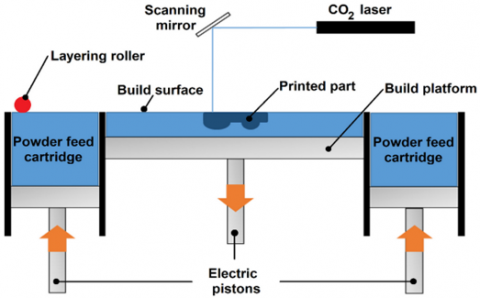
The process of selective laser sintering, often known as SLS, is a kind of three-dimensional printing that makes use of a laser to fuse together microscopic particles of material, such as nylon or polystyrene, into a solid item. The laser is pointed in the direction of a powder material bed; as it does so, it selectively sinters or melts and fuses the particles together. This process builds the thing up layer by layer. This technology has the ability to manufacture components with a high level of precision, a wide variety of materials, a high level of manufacturing volume, and a low level of material waste, as well as solid and durable parts with a quick turnaround time [1].
The SLS procedure is broken down into parts and illustrated in Figure 1, and it provides a more comprehensive and in-depth review of the SLS procedure [2].
Many issues might arise during the printing process, affecting the final quality and attributes of the printed object. Warping or delamination, porosity, part distortion, surface quality, incomplete sintering, and refocusing issues are examples of these challenges [3]. These issues can be caused by various circumstances, including bad material selection, poor design, and wrong process settings. It is critical to recognize the potential issues that may arise during the SLS process and to take action to mitigate them.
The rate at which the laser moves, known as the scanning speed, is a vital aspect that needs careful control in the SLS process [4]. This speed influences how the laser fuses the powder in the bed, directly impacting the efficiency and quality of the SLS production. A higher scanning speed can increase production efficiency but may compromise the surface quality of the final product.
When the scan rate is increased, it leads to a bigger melt pool, potentially causing issues like warping, porosity, and distortion. Moreover, quicker scanning can induce thermal stresses, adversely affecting the final product's mechanical characteristics.
Conversely, a slower scanning speed tends to enhance the surface quality and mechanical integrity of the end product, though it might reduce overall production speed. Therefore, it's essential to strike a balance between production rate and quality when setting the scanning speed, which varies depending on the material and design of the product being printed.
Figure 1. Schematic view of the SLS process
To grasp and manipulate the parameters involved, it's essential to model the process comprehensively. This enables a deeper understanding of the basic physical principles governing the SLS process. Moreover, it facilitates the prediction of how both the powder bed and the fabricated parts will behave under various processing conditions.
Within literary works, several numerical methodologies have been applied to simulate the SLS process. The most prevalent among these include Finite Element Method (FEM), Finite Difference Method (FDM), Lattice Boltzmann Method (LBM), and Computational Fluid Dynamics (CFD) models. These approaches are instrumental in addressing various aspects of the SLS process.
The bulk of existing studies aims to analyze and optimize different facets such as heat transfer, fluid flow, and process parameters, including laser power and scanning speed. The ultimate goal of these studies is to predict the thermal behavior, residual stresses, and deformations in the objects being printed.
Küng et al. [5] introduced a model based on the Lattice Boltzmann method to simulate the SLS process for binary alloys. This model integrates specific thermodynamic and mass conservation elements for each element and incorporates enthalpy diffusion, laying a foundation for understanding the intricacies of thermal behavior in the printing process.
Building upon this foundation, Yaagoubi et al. [6] employed a three-dimensional finite element method using COMSOL Multiphysics software to predict temperature distribution within the initial layer of polyamide formed during the SLS process. Observing temperatures surpassing the liquidus temperature due to energy concentration from the laser spot, their work adds to the comprehension of temperature dynamics at the microscale.
Furthering the understanding of thermal dynamics, Li et al. [7] utilized a transient three-dimensional thermal model to investigate the SLS process of PA6. Their model, implemented in ABAQUS software, comprehensively captures material thermal behavior during laser projection. Through validation via single-layer sintering experiments, they optimized process parameters, ensuring a balance between melt pool depth and maximum temperature, crucial for quality printing.
Similarly, Dong et al. [8] developed a transient three-dimensional finite model to simulate the SLS process applied to various powders. Integrating thermal and sintering phenomena, their model, validated with experimental results, elucidates the influence of process parameters on temperature and density distribution in the powder bed, contributing to process optimization efforts.
Expanding the scope beyond thermal considerations, Russell et al. [9] employed a Smooth Particle Hydrodynamics (SPH) approach to simulate thermal-mechanical-material fields in additive manufacturing processes. Addressing track deposition physics and processing settings' impact on melt track quality, their work highlights the interconnected nature of process variables in achieving desired outcomes.
Additionally, Ly et al. [10] conducted detailed experiments and finite element modeling of metal micro-droplet motion in metal additive manufacturing processes. By examining droplet ejection dynamics and laser powder bed interactions, their study deepens insights into the physics underlying additive manufacturing processes.
The same numerical method (FEM) is used by Foroozmehr et al. [11], which simulated a single layer of 316L stainless steel on a thick powder bed to predict the melt pool size when printing parts.
We also have the experimental work of El Magri et al. [12], which examined the influence of two selective laser sintering (SLS) parameters, laser power and hatch orientation, on the physical properties of parts made from Polyamide 12 (PA12).
However, despite the significant contributions of the aforementioned research and modeling efforts, they are inherently limited in accurately capturing the complexities of the selective laser sintering process. These limitations primarily stem from the utilization of continuum-based modeling approaches, which assume homogeneity within the powder bed, thereby neglecting its discrete and particulate nature. Consequently, such methods fail to provide detailed insights into the medium during simulation, leading to an underestimation of the impact of air within the medium and a lack of detection regarding the individual behavior and outcomes of each particle within the powder bed. This deficiency underscores the inadequacy of continuum methods for effectively simulating discontinuous and granular media, where detailed analysis of particle interactions and behavior is paramount.
Moreover, the behavior of the powder bed in SLS is intricately influenced by the unique properties of individual particles and their interactions, including forces and contacts between particles, which are inherently challenging to capture accurately using continuous methods. The practical limitations of continuous approaches become apparent, as they struggle to adequately account for the complexities inherent in particle systems, ultimately hindering their efficacy in accurately modeling the SLS process.
In comparison, the discrete element method (DEM) emerges as a promising alternative for modeling the selective laser sintering process. DEM is a numerical technique specifically designed to simulate the behavior of granular materials, including powders, granules, and granular assemblies [13]. Unlike continuum-based methods, DEM represents granular materials as a collection of discrete particles, each possessing its own distinct properties and interactions. These particles interact with each other and with the boundaries of the container in which they are contained, allowing for a more accurate representation of the complex dynamics within the powder bed.
The inherent suitability of DEM for simulating SLS lies in its capacity to capture the discontinuous and particulate nature of the powder bed, a characteristic that is essential for accurately modeling the SLS process. By explicitly modeling the individual particles and their interactions, DEM offers a more realistic depiction of the behavior of the powder bed during laser sintering. This includes accounting for phenomena such as particle rearrangement, compaction, and agglomeration, which play pivotal roles in determining the quality and characteristics of the printed parts.
In a DEM simulation, the powder bed is represented as a collection of discrete particles, and the interactions between the particles are modeled using mathematical equations. In this way, researchers can predict how the powder bed will behave under different process conditions, such as laser power, scan speed, and layer thickness.
This method allows researchers and engineers to test different process parameters and material combinations to optimize the SLS process and predict how the final product will behave. It can also provide valuable insights into the underlying physical mechanisms of the SLS process, which can help improve the process and increase the reliability of printed parts.
The suitability of DEM to the SLS process is demonstrated in our published work [14], where we proposed a DEM-based modeling framework for the thermal simulation of the process under the static action of a laser beam.
The results matched well with the experimental data obtained by Lanzl et al. [15] and the FEM results obtained via Yaagoubi et al. using the COMSOL program [6].
This paper aims to develop a compact computational framework for the SLS process using the discrete element method. It integrates essential physics and efficient computation to accurately simulate the melting of powder bed particles by a moving laser source.
Our framework outlines the methodologies and calculations needed for Python implementation (detailed in section 2), focusing on analyzing temperature distribution within a Polyamide 12 (PA12) powder bed across various scanning speeds during the powder line melting phase. We aim to benchmark these findings against those from [16], which utilized the Lattice Boltzmann method for simulating the identical SLS process under the same manufacturing parameters.
Additionally, our secondary investigation assesses how laser power and speed influence the fused surface size, juxtaposing our findings with visualizations derived via the same numerical approach in the study [16], thereby enriching our comparative analysis and understanding of the SLS process's dynamics.
The Proposed Approach and discrete element method are described in the following Section. The section also provides a synopsis of the suggested methodology. The findings and analysis are presented in Section 3. The paper is concluded in Section 4.
In the preceding discussion, the potential of the discrete element method, often known as DEM, in replicating powder-based stacking was brought to light. In order to make the most of the capabilities of this technology, a thorough algorithm has been devised. This algorithm incorporates the appropriate DEM formulation in order to simulate the SLS process in a manner that is both precise and efficient.
This multi-particle DEM framework addresses several major physical events in the fusion process, including:
•Particle dynamics: This aspect of the simulation focuses on the motion of particles caused by contact between particles and surfaces, as well as the forces that arise between particles as a result of these interactions. The algorithm accounts for the complex behavior of particles as they collide and deform, providing a physically realistic simulation.
•Laser input: The algorithm also considers the absorption of the supplied laser energy by particles. The laser input is modeled in a way that accurately reflects the physical behavior of the particles and their interactions with the laser.
•Thermodynamics of particles: The algorithm also models the heat transfer between particles that occurs through conductive contact. As a result of this heat transfer, particles may experience thermal softening, which can significantly affect the particles' dynamics and behavior. The algorithm accounts for these effects, providing a more realistic simulation of the thermodynamics of particles.
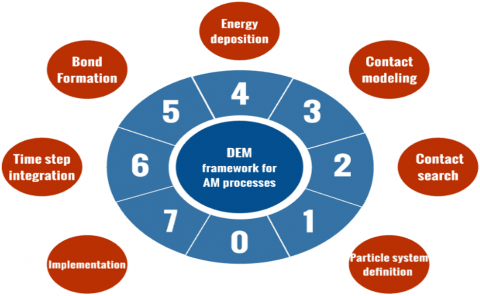
The simulation of the selective laser sintering process through the discrete element method incorporates several essential tasks designed to accurately replicate the associated physical phenomena. These operations have been methodically organized and are depicted in Figure 2, which outlines the details of our DEM simulation framework. The subsequent sections provide a comprehensive examination of the mathematical formulations implemented in our Python code, specifically tailored for each DEM modeling task. This detailed approach ensures that each step of the simulation process is grounded in rigorous mathematical principles, allowing for a more accurate and effective representation of the SLS process in our computational model.
Figure 2. The tasks required for the simulation of the SLS process by the DEM
2.1 Particle system definition
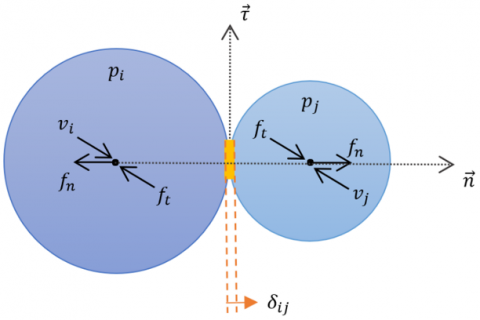
A simulation that utilizes the discrete element method (DEM) involves many particles of varying shapes, such as spheres, cylinders, and polygons, that interact with each other or with a bounding plane. These interactions can include collisions, rolling, and sliding. These interactions result in reaction forces, such as normal and tangential forces, that affect the position and velocity of the particles. These forces can cause the particles to change direction, speed up, or slow down.
As shown in Figure 3, these interactions and forces are represented by various variables, such as position $\left(p_i\right)$, velocity $\left(v_i\right)$, tangential force $\left(f_t\right)$, and normal force $\left(f_n\right)$, which are used to track the movement and behavior of the particles in the simulation. The normal and tangential directions are denoted by $\vec{n}$ and $\vec{\tau}$, respectively, and $\delta_{i j}$ represents the overlap between particles $i$ and $j$.
It's important to note that while Figure 3 and Figure 4 depict spherical particles, this representation may not always be accurate. In many cases, the particles in a simulation may not be spherical and can be irregular shapes such as cylinders, polygons, etc. [17]. Contact stiffness, which is the measure of the resistance of an object to deformation when a force is applied, is dependent on local curvature, and this can vary significantly between spherical and non-spherical particles. Additionally, interactions between non-spherical particles, such as friction, rolling, and sliding, generate tangential forces and moments that can significantly affect the particles' motion and behavior. Therefore, it should be used with caution when assuming all particles to be spherical, as this approximation may not be universally applicable in all cases.
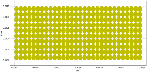
Figure 4 illustrates a structural visualization of the particulate system in the powder bed within our DEM simulation. This visualization explains how the particles are arranged and organized in the bed, where the grains are seen to be evenly distributed.
The simulation time variable is $\tau$, the simulation time step is $\Delta \tau$, and $n_\tau$ is the total number of iterations in the simulation. The time step selection must consider various factors, including the duration of the simulation. Longer time steps are necessary for more extended simulations, while smaller ones are required for more detailed and precise solutions.
The available range of time steps is determined by the selected integration method. In explicit methods, which are the most commonly used, the critical time step imposes a limit on the time step selection.
An exciting work by Rougier et al. [18] contains a comparative study of the explicit time integration schemes commonly used in the discrete element method.
Figure 3. Parameters and mechanism of contact between particles in a powder bed
Figure 4. Representation of the particulate system within the powder bed in our DEM simulation
2.2 Contact search
The discrete element method (DEM) differs from continuous methods in that there are no connections between nodes through elements. This means that properties such as forces and accelerations, velocities, and displacement can be transferred through contact criteria between pairs of elements.
Contact search is a crucial component of the method in terms of computational cost, often taking up 60-80% of simulation time, and can be particularly challenging when dealing with non-spherical/circular particles. To reduce simulation time, an approach that limits contact search is necessary.
Due to the poly-dispersity of the particle system, where the difference between the maximum and minimum size is greater than ten, collision detection can be divided into two steps. Additionally, it is assumed that all particles are spherical. Various algorithms can be employed for contact search to minimize the contact search required to lower the simulation duration. Literature on collision detection methods can be found in references [19-23].
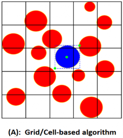
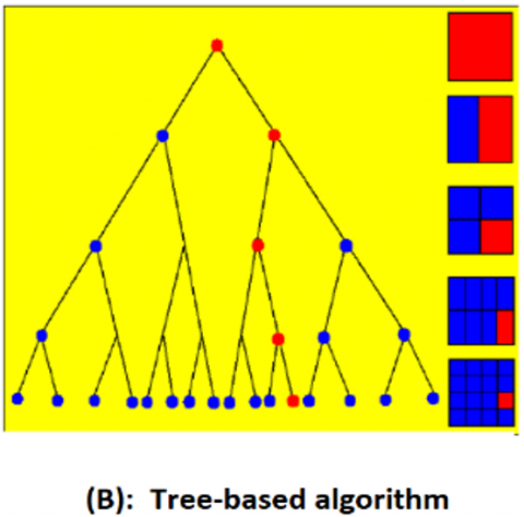
The most frequently employed techniques for collision detection are grid-based and tree-based algorithms [24], both of which have multiple forms and variations. The structure of these algorithms is outlined in Figure 5.
(A) Grid-based techniques: This method divides the simulation space into a grid of cells, and particles are assigned to the appropriate cell based on their position. When a particle moves, it is reassigned to the appropriate cell. This method is efficient but can lead to errors if the cell size is not chosen correctly.
(B) Tree-based techniques: These algorithms divide the simulation space into smaller regions, such as octrees or bounding volume hierarchies, and particles are assigned to the appropriate region based on their position. This method is more accurate than grid-based techniques but can be computationally expensive.
In our DEM simulations, collision detection plays a critical role in identifying particle interactions. Each particle, denoted as particle 'i', is associated with a unique list, $L_i$, which contains the indices of other particles that come within a pre-defined proximity, indicating a collision.
A collision is considered to have occurred when the distance between two particles is less than the collision radius. The distance between the particles is computed using the following equation:
$L_i=\left\{j:\left\|p_i-p_j\right\| \leq d_i\right\} ; d_i=r_i+r_j$ (1)
where, $\left\|p_i-p_j\right\|$ represents the normalized Euclidean distance between particles $i$ and $j$, and $d_i$ is the collision radius, calculated as the sum of the radii of the tested particles.
This collision detection framework underpins the subsequent application of contact laws, ensuring that physical interactions between particles are accurately captured and analyzed within our simulations.
Figure 5. Collision detection algorithms in DEM simulations
2.3 Contact modeling
In this section, we present the laws that govern the physical interactions between particles in the powder bed, based on the lists of contacts identified in the previous section.
We differentiate two types of contact laws in the powder bed: the contact law be-tween the particles and the contact law with the boundary plane. These laws describe the mechanical and thermal interactions within the medium.
2.3.1 Inter-particle contact law
Mechanical contact law:
When two discrete particles come into contact, it transmits forces to each of these particles. These forces oppose the relative motion of each particle to its neighbor in both normal and tangential directions.
The connection is defined geometrically by a line passing through the centers of the two particles $i$ and $j$. A unit vector $\vec{n}$ is defined in the same direction as this line. The direction of the parameters involved in the contact mechanism is depicted in Figure 3.
Building upon the principles established by researchers [14, 25], we integrate advanced formulations into our DEM simulations to characterize the interactions between particles. Specifically, the mechanical contact laws for calculating the normal and shear forces between two particles, i and j, have been refined to include damping effects, enhancing the simulation's accuracy:
$f_{n_{i j}}=-K_n . \delta_{i j} . \vec{n}-c_n . v_{i j} . m^*$ (2)
$f_{t_{i j}}=-\mu_c\left\|f_{n_{i j}}\right\| \frac{\left(v_i-v_j\right)}{\left\|v_i-v_j\right\|}$ (3)
In this context, $c_n$ refers to the damping coefficient, and $v_{i j}$ denotes the relative normal velocities. The effective mass is represented as $m^*=m_i m_j /\left(m_i+m_j\right)$, where $m_k$, for $k$ in $\{i, j\}$, signifies the mass of the k-th particle. Additionally, $\delta_{i j}$ represents the penetration distance between particles $i$ and $j$, computed using the following formula:
$\delta_{i j}=d_i-\left\|p_i-p_j\right\|$ (4)
where, $d_i$ is the sum of the radii of the particles in contact, already utilized in the collision detection process (refer to section 2.2), $\left\|p_i-p_j\right\|$ represents the Euclidean distance between the centroids of particles $i$ and $j . K_n$ is the normal stiffness coefficient, $\mu_c$ represents the Coulomb friction coefficient, and $v_i$ and $v_j$ are the velocity vectors of particles $i$ and $j$.
Therefore, the total force $\left(f_i\right)$ exerted on particle $i$ is the sum of all the normal and tangential forces exerted by the neighboring particles.
$f_i=\sum_j\left(f_{n_{i j}}+f_{t_{i j}}\right)$ (5)
Thermal contact law:
In our DEM simulation, particle interactions lead not only to mechanical impacts but also to significant thermal exchanges, as modeled based on methodology of the study [26], focusing solely on conduction for heat transfer between particles. This specific thermal interaction, separate from mechanical forces, is vital for a precise depiction of powder bed dynamics in SLS processes. Governed by Fourier's law, the heat transfer is quantified as:
$\mathrm{q}_{\mathrm{ij}}=\lambda_{\mathrm{c}}\left(\mathrm{T}_{\mathrm{j}}-\mathrm{T}_{\mathrm{i}}\right)$ (6)
where, $\lambda_c$ represents the heat conduction between the particles and $\mathrm{T}_{\mathrm{i}}$ and $\mathrm{T}_{\mathrm{j}}$ are the temperatures of particles $i$ and $j$. The heat absorbed by particle $i$ as a result of contact with another particle can be succinctly represented as:
$q_i=\sum_{j=1}^{n_c} q_{i j}$ (7)
where, $n_c$ indicates the number of contacts formed by particle $i$.
2.3.2 Contact law with the boundary planes
Mechanical contact law:
In our DEM framework, the interaction dynamics between a particle and a boundary plane (wall) are modeled with the same principles as those between individual particles. This consistency ensures a unified approach to force calculations across the simulation. Specifically, we focus on the normal force exerted by the wall on particles, which is the force acting perpendicular to the surface of the wall, denoted as (k).
This normal force is added to the force of the particles to update their position and velocity. To do this, the distance between the particles and the wall must be calculated $\left(x_i\right)$, and the force with the walls is determined using the following equation:
$f_{n_{i, k}}=k_b \cdot \beta \cdot \overrightarrow{n_k} ; \beta=\left\{\begin{array}{c}0 \text { if } x_i \geq r_i \\ r_i-x_i \text { if } x_i<r_i\end{array}\right.$ (8)
The distance between particle $i$ and the wall is represented by $x_i, \overrightarrow{n_k}$ is the normal unit vector of the boundary surface, and $k_b$ is the boundary stiffness.
Thermal contact law:
In our DEM simulations, we approach heat transfer between particles and walls identically, treating it as strictly conductive to maintain consistency and simplicity. However, for particles at the upper surface, the scenario differs; they experience heat exchange with the chamber's internal air through both convection and radiation, acknowledging the distinct thermal environments experienced by these particles compared to those fully embedded within the powder bed.
In the case of wall transfer, a conduction heat flow is added to particle i, which is described by the following equation:
$q_i+=\lambda_{c b}\left(T_w-T_i\right)$ (9)
For heat transfer on the top surface, particle i receives a heat flow through both convection and radiation, represented by the following equation:
$q_i+=h_c\left(T_a-T_i\right)+\zeta \cdot \sigma_{S B} \cdot\left(T_a{ }^4-T_i^4\right)$ (10)
where, $T_w$ and $T_a$ represent the temperatures of the wall and fabrication chamber respectively. $\lambda_{c b}$ is the conduction coefficient with the wall, $h_c$ is the convection coefficient with the chamber, $\zeta$ is the emissivity of the material, and $\sigma_{S B}$ is the Stefan-Boltzmann constant.
2.4 Energy deposition
Powder-based additive manufacturing processes involve using a laser source to transfer energy in order to create a physical object. The position of the laser source can be changed depending on the desired scanning strategy.
This means that the laser beam can be moved to different locations and angles in order to achieve the desired final product. The motion of the laser beam is described mathematically by a function, denoted by $\varphi(\tau)$, which specifies the exact coordinates of the laser at each time step.
$\varphi(\tau)=\left\{\begin{array}{cc}\varphi_0(\tau), & 0 \leq \tau<\tau_0 \\ \varphi_1(\tau), & \tau_0 \leq \tau<\tau_1 \\ \cdot \\ \cdot \\ \varphi_n, & \tau_{n-1} \leq \tau<\tau_n\end{array}\right.$ (11)
The laser beam scans a group of particles in a powder bed at each time step. The absorption of the light, or flow, by these particles is studied and modeled in academic literature [27, 28]. One common model used is the cylindrical and Gaussian thermal flow model, which considers the shape and distribution of the flow within the powder bed.
In our DEM simulation, we will use the Gaussian model to represent the heat distribution in the laser beam. This is an improvement over previous work that has been published [14], as the Gaussian model provides a more accurate representation of how the flow spreads in the powder bed. This is because the Gaussian model accounts for the natural propagation and decay of the flow as it moves through the powder. The following equation characterizes the Gaussian model:
$q_0(r)=\frac{2 P}{\pi r_l^2} \cdot e^{-2 r^2 / r_l^2}$ (12)
where, $r_l$ is the laser beam radius, and $P$ is the laser power.
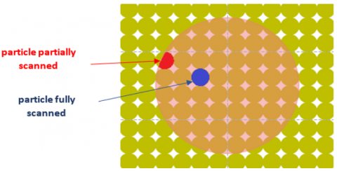
As a result of the laser beam scanning, the particles in the powder bed absorb an additional amount of heat flow. The amount of heat flow absorbed by each particle is not uniform, it varies depending on the particle's distance from the center of the laser beam and if the particle is wholly or partially scanned, as illustrated in Figure 6.
$q_i+=\left\{\begin{array}{cc}q_0 * \frac{S_i}{S_l}, & 0 \leq\left\|p_i-\beta_l\right\| \leq r_l-r_i \\ q_0 * \frac{S_{\text {inter }}}{S_l}, & r_l-r_i \leq\left\|p_i-\beta_l\right\| \leq r_l+r_i \\ 0 & \text { otherwise }\end{array}\right.$ (13)
The distance between particle $i$ and the center of the laser beam is represented by $\left\|p_i-\beta_l\right\|$, while $S_i$ represents the area of particle $i, S_l$ represents the area of laser sintering, $S_{\text {inter}}$ represents the interface between the particle and the heat input area. The total energy absorbed by all sintered particles is described by $q_0$, which is distributed among these particles according to their sintering area ratio.
Figure 6. Visualization of the particles in the powder bed as the laser beam scans them
2.5 Bond formation
After the energy is applied, the particles form bonds with their neighbors. These bonds are determined by specific formation criteria and are stored in a list $B_i$, which lists the indices of particles that are bonded to particle $i$. To collect these connections, we use the contact list $\left(L_i\right)$ as outlined in Section 2.2, which defines the contacts of particle $i$.
The criteria for the formation of links or bonds between particles include the following:
$f_{\text {crit }}, v_{\text {crit }}$ and $T_s$ are critical criteria that vary for each material used in the SLS process.
2.6 Time step integration
Upon computing the physical interactions affecting each particle within our DEM framework, it is essential to extend these impacts temporally. For this purpose, we employ explicit time integration schemes tailored for DEM simulations, as detailed in reference [18].
The same update scheme used in the work of Lakraimi et al. [14] is applied as follows:
$\begin{gathered}v_i(\tau+\Delta \tau)=v_i(\tau)+\frac{f_i(\tau)}{m_i} \Delta \tau \\ p_i(\tau+\Delta \tau)=p_i(\tau)+v_i(\tau) \Delta \tau \\ T_i(\tau+\Delta \tau)=T_i(\tau)+\frac{q_i(\tau)}{m_i * c_p} \Delta \tau\end{gathered}$ (14)
where, $m_i$ and $c_p$ represent the mass and the mass heat capacity of particle $i$, respectively.
2.7 Implementation
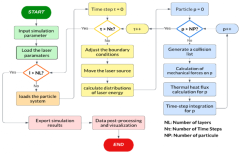
The methodology elaborated in previous sections, which outlines the conceptual framework of our DEM simulation, is systematically organized and depicted in Figure 7. This figure illustrates the comprehensive algorithm developed for simulating the SLS process via the discrete element method. This algorithm, as showcased in Figure 7, has been effectively implemented and visualized utilizing the Python programming language.
Figure 7. The general framework for simulating the SLS process under the projection of a moving laser source
Melting a single line of powder is a simple and commonly used method to study the consolidation characteristics of the powder when exposed to a moving heat source. This simulation allows for observing how the powder melts and solidifies as the heat source moves along the line, providing insights into the powder's behavior during the consolidation process.
In this section, we will use the provided DEM framework to simulate the thermal effects of a moving laser projection on an SLS powder bed. We will specifically examine the impact of varying the laser source's spatial position and power on the maximum temperature of polyamide 12 (PA12) powder, a commonly used material in SLS [29-31], with the goal of understanding the impact of these parameters on the fused surface.
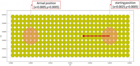
The beam begins at the starting point of (x=0.0025, y=0.0005) and follows a straight line to the final position (x=0.0005, y=0.0005), as depicted in Figure 8, which illustrates the laser beam's path.
Our simulation is designed to recreate the environment from an earlier research conducted by Osmanlic [16]. In their study, they utilized an innovative approach that combines the Lattice Boltzmann method for thermal viscoelastic simulation of free surface flows with a ray tracing model to evaluate laser absorption within a powder bed. The specifics of the parameters applied in both the original and our replicated simulations are clearly outlined in Table 1.
In Figure 9, we present a detailed examination of the temperature variation within the melt line, utilizing the discrete element method (DEM) for our analysis. The simulation parameters, as indicated in Table 1, include a scanning speed of 0.5m/s. At the specific time marker τ=0.002 seconds, we observe that the laser has reached the central point of the melt line. This moment in the simulation is critical as it shows the initial interactions between the laser and the powder bed; the area directly influenced by the laser exhibits a significant increase in temperature.
Figure 8. The path of the laser beam in the powder bed
Table 1. The parameters applied in the computations displayed in Figure 9
|
Parameters |
Value |
|
Laser power (P) |
5W |
|
Laser speed (V) |
0.5m/s; 1m/s |
|
The preheating temperature of the powder ($T_i$) |
173℃ |
|
The temperature of the chamber ($T_a$) |
173℃ |
|
Laser beam radius ($r_l$) |
200μm |
|
Particle radius ($r_i$) |
50μm |
|
Laser path length (l) |
2mm |
|
The time step ($\Delta \tau$) |
0.0005s |
|
The density of the powder (ρ) |
1000kg/m3 |
|
Thermal conductivity (λ) |
0.28W/m.K |
|
Domain porosity (ε) |
0.78(DEM) |
|
Stefan-Boltzmann coefficient ($\sigma_{S B}$) |
5.67×10⁻⁸ |
At this juncture, the sintering process is predominantly localized, affecting only those particles that are directly in the path of the laser. This selective sintering results in a peak temperature of approximately 350℃ within the targeted zone. It's important to note that at this early stage, thermal conduction to the surrounding particles is minimal, which means the heat impact is confined strictly to the particles hit by the laser.
As time progresses and the simulation continues, the sintering dynamics begin to evolve. The temperature distribution across the powder bed becomes more uniform, a clear indicator of the advancing sintering process. By this point, the maximum temperature escalates to around 458℃ at the beam's epicenter. This particular temperature profile corresponds well with the theoretical predictions based on the Gaussian absorption model, which is thoroughly discussed in Section 2.4 of the accompanying text.
Figure 9. Temperature progression using a scan speed of 0.5 m/s and the values listed in Table 1 for two separate times
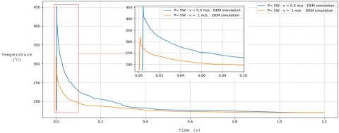
Figure 10. The evolution of the maximum temperature in the powder bed at two scanning speeds (0.5m/s; 1m/s) using the parameters listed in Table 1
Figure 10 illustrates an in-depth analysis of time-dependent temperature changes within the melt, as influenced by different scanning rates during the laser sintering process, utilizing the base parameters from Table 1 alongside an altered set where the scanning speed is increased to V=1m/s.
In scenarios where the scanning speed is heightened to V=1m/s, the temperature trace exhibits a pronounced peak that materializes more swiftly compared to the slower scanning rate. This accelerated peak occurrence is attributed to the laser beam traversing the simulation domain at a faster pace. Consequently, the maximum temperature attained at this increased speed is notably lower. This reduction in peak temperature is due to the reduced energy absorption by the material; specifically, at a scanning speed of 1m/s, the material absorbs only half the amount of energy compared to when the scanning speed is set at 0.5m/s.
Following the laser irradiation period, there is a noticeable decline in the peak temperature, which can be attributed to thermal diffusion and convection mechanisms within the melt. This cooling phase continues until the temperature stabilizes, ultimately reverting to the initial preheating level. At this juncture, temperature uniformity is achieved throughout the powder bed, signifying the attainment of thermal equilibrium.
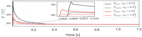
Figure 11. Evolution of the maximum and mean temperature in the study [16] based on the parameters presented in Table 1
To ensure the accuracy and reliability of our simulation framework for SLS process, we will conduct a validation exercise. This involves comparing the results obtained from our DEM simulations with those documented in study [16], which employed the Lattice Boltzmann Method (LBM) under identical parameters to those we used in our DEM simulations (as detailed in Table 1).
Specifically, Figure 11 illustrates the temperature changes that occur during the melting process of a powder line. These changes were initially modelled using the Lattice Boltzmann thermal viscoelastic method, under the same conditions we applied in our DEM simulations. When we juxtapose the outcomes represented in Figures 10 and 11, we observe a remarkable degree of correspondence between the findings of the two distinct approaches.
The comparison reveals that the progression of temperature throughout both the melting and subsequent cooling stages aligns closely between the two methods, with a negligible variance observed at the peak temperature point-a variance deemed minor and within acceptable limits. This close match not only attests to the robustness and accuracy of the DEM approach but also reinforces its credibility and compatibility with existing methods documented in the literature for effectively simulating the SLS process.
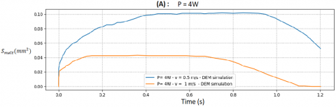
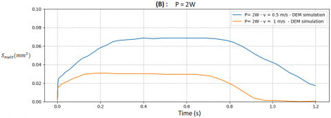
The second study employs our DEM framework to analyze the impact of laser power and speed on the powder bed's molten surface. The simulation replicates the conditions and parameters from the first part (Table 1) while exposing the melt pool to two laser powers (2W, 4W) and two scanning speeds (0.5m/s, 1m/s). The size of the melt pool's evolution is displayed as curves for each laser power and scan speed in Figure 12.
Figure 12 delineates the intricate progression of the melt pool size during the laser sintering process, a phenomenon segmented into four distinct phases to facilitate a clearer understanding.
In the first phase, we observe an immediate expansion of the melt pool. This rapid enlargement is primarily attributed to the laser's initial interaction with the powder bed, where the material starts absorbing energy at a significant rate. During this period, radiation transport plays a critical role in energy distribution, leading to a quick increase in the size of the melt pool.
Transitioning to the second phase, the growth rate of the melt pool decelerates. This slowdown is due to a shift in the dominant energy transport mechanisms from radiation to conduction and convection. In this stage, energy transfer occurs mainly through direct contact and fluid motion among the powder particles, resulting in a more gradual expansion of the melt area.
In the third phase, the system begins to reach a state of temperature equilibrium. The powder particles, now undergoing extensive sintering, contribute to a more uniform energy distribution across the powder bed. This phase is characterized by the establishment of a homogeneous thermal field, leading to a stabilized expansion of the melt pool.
The final phase marks the conclusion of the melting process, where energy dissipation becomes the focal point. The melt pool begins to solidify as energy is efficiently conducted away to the manufacturing plate and lost via convection to the surrounding environment of the manufacturing chamber. This results in the cessation of melt pool expansion and the solidification of the melted material.
Figure 12. The evolution of the melting pool size under the effect of two laser powers (A: 2W, B: 4W) and two scanning speeds (0.5m/s, 1m/s)
Furthermore, the evolution curves of the melt pool size within Figure 12 provide critical insights into the effects of varying process parameters. Notably, an increase in laser power, while maintaining a constant scanning speed, results in a more substantial energy absorption and thus a larger melt pool. Conversely, an increase in scanning speed with constant power reduces the energy absorption, leading to a decrease in melt pool size. Specifically, under parameters of V=1.0m/s and P=2.0W, the energy absorbed is insufficient for significant melting, preventing the formation of a proper melt bead. By increasing the energy input-either through enhancing power or adjusting other parameters-a larger and more functional melt pool can be achieved, as demonstrated in the detailed analytical curves depicted in the figure.
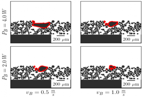
The visual representation captured in Figure 13 is integral to understanding the dynamics of the melt bath within the powder bed, as investigated through our DEM simulations. These simulations adhere to parameters that align with those referenced in study [16], ensuring consistency in our comparative analysis.
Figure 13. Visualizing the melt size impacted by two laser powers and scanning speeds performed by the study [16]
Figure 13 is marked by a prominent red line, denoting the boundary of the melt bath. This delineation is critical for visualizing the extent of the melted region and for interpreting the effects of varying energy inputs on the sintering process. By scrutinizing the depicted melt bath, we can draw parallels to the observations made in Figure 12, reinforcing our understanding of the relationship between energy input and the consequential alterations in the size of the melt bath.
The comparison between Figures 12 and 13 underscores the tangible effects of modifying energy input parameters. These effects are manifested in the alterations of the melt bath's size and shape within the powder bed, vividly illustrated through the distinct boundary marked by the red line in Figure 13.
In our research, we explored the sensitivity of the discrete element method (DEM) simulation results to variations in key SLS process parameters, specifically laser power and scanning speed. Despite systematically varying these parameters within the tested ranges, our simulation outcomes remained consistent, showing no significant alteration in the temperature distribution and size of the melt pool. This finding indicates a high degree of robustness of our DEM model under varying operational conditions. These results were further corroborated by the study [16], which demonstrated great adequacy and alignment with our findings, thus reinforcing the reliability and stability of our simulation approach in depicting the selective laser sintering process dynamics under different laser settings.
The findings from both investigations, supplemented by a comprehensive comparison with existing literature, underscore the significant promise of the DEM in simulating the SLS process. The research demonstrated DEM's adeptness in reflecting the effects of varying power and velocity on the powder bed's behavior during the melting phase. These capabilities underscore the method's considerable potential for detailed and realistic modeling of the SLS process.
However, despite its promising attributes, the current application of DEM in simulating the SLS process is not without its limitations. One notable area for improvement lies in expanding the scope beyond purely thermal modeling to include mechanical modeling. This enhancement is crucial for a more comprehensive and accurate representation of the SLS process, encompassing both heat transfer and mechanical behavior under different operational conditions.
These preliminary findings, while showcasing the method's considerable capabilities, also highlight the imperative need for development. They serve as a strong motivation for us to advance our research by developing a more sophisticated code that integrates thermomechanical modeling. Such advancements will not only address the current limitations but also broaden the applicability and accuracy of DEM in simulating the complex phenomena involved in the SLS process, paving the way for more detailed, accurate, and comprehensive models in the future.
In this study, we introduced a novel computational framework leveraging the discrete element method (DEM) specifically tailored for simulating the selective laser sintering (SLS) process. This approach marks a significant departure from traditional continuous simulation methods by accurately capturing the discrete, granular nature of powder beds, thus addressing a fundamental challenge in additive manufacturing research.
The development and implementation of this DEM-based modeling framework provide a new lens through which the interactions between the laser heat source and polyamide 12 powder particles are viewed, offering unprecedented insights into the SLS process. This includes a detailed analysis of how variations in laser power and scanning speeds influence the melting behavior and temperature distribution within the powder bed, enabling the optimization of these parameters for improved manufacturing outcomes.
Our research further validates the effectiveness and reliability of the DEM approach in simulating the SLS process. By comparing our findings with existing literature, we have demonstrated that the DEM can overcome the limitations inherent in continuous methods, offering a more accurate and nuanced understanding of the dynamics at play.
This work lays a solid foundation for future investigations, offering a comprehensive framework that can be expanded to include a broader range of SLS parameters. The implications of our findings extend beyond the theoretical, offering practical insights and tools that can be employed by researchers and practitioners alike to enhance the precision, efficiency, and reliability of additive manufacturing processes.
[1] Natarajan, J. (Ed.). (2021). Advances in Additive Manufacturing Processes. Bentham Science Publishers.
[2] Yan, C., Shi, Y., Zhaoqing, L., Wen, S., Wei, Q. (2020). Selective Laser Sintering Additive Manufacturing Technology. Academic Press. https://www.elsevier.com/books/selective-laser-sintering-additive-manufacturing-technology/yan/978-0-08-102993-0.
[3] Sefene, E.M. (2022). State-of-the-art of selective laser melting process: A comprehensive review. Journal of Manufacturing Systems, 63: 250-274. https://doi.org/10.1016/j.jmsy.2022.04.002
[4] Cheng, B., Price, S., Gong, X., Lydon, J., Cooper, K., Chou, K. (2014). Speed function effects in electron beam additive manufacturing. In ASME International Mechanical Engineering Congress and Exposition. American Society of Mechanical Engineers, 46438: V02AT02A003. https://doi.org/10.1115/IMECE2014-36664
[5] Küng, V.E., Scherr, R., Markl, M., Körner, C. (2021). Multi-material model for the simulation of powder bed fusion additive manufacturing. Computational Materials Science, 194: 110415. https://doi.org/10.1016/j.commatsci.2021.110415
[6] Yaagoubi, H., Abouchadi, H., Janan, M.T. (2021). Numerical simulation of heat transfer in the selective laser sintering process of Polyamide12. Energy Reports, 7: 189-199. https://doi.org/10.1016/j.egyr.2021.08.089
[7] Li, M., Han, Y., Zhou, M., Chen, P., Gao, H., Zhang, Y., Zhou, H. (2020). Experimental investigating and numerical simulations of the thermal behavior and process optimization for selective laser sintering of PA6. Journal of Manufacturing Processes, 56: 271-279. https://doi.org/10.1016/j.jmapro.2020.04.080
[8] Dong, L., Barth, N., Correia, J.P.M., Ahzi, S. (2016). Modeling and numerical simulation of selective laser sintering. In 2016 17th International Conference on Thermal, Mechanical and Multi-Physics Simulation and Experiments in Microelectronics and Microsystems (EuroSimE), Montpellier, France, pp. 1-4. https://doi.org/10.1109/EuroSimE.2016.7463376
[9] Russell, M.A., Souto-Iglesias, A., Zohdi, T. (2018). Numerical simulation of Laser Fusion Additive Manufacturing processes using the SPH method. Computer Methods in Applied Mechanics and Engineering, 341: 163-187. https://doi.org/10.1016/j.cma.2018.06.033
[10] Ly, S., Rubenchik, A.M., Khairallah, S.A., Guss, G., Matthews, M.J. (2017). Metal vapor micro-jet controls material redistribution in laser powder bed fusion additive manufacturing. Scientific Reports, 7(1): 4085. https://doi.org/10.1038/s41598-017-04237-z
[11] Foroozmehr, A., Badrossamay, M., Foroozmehr, E., Golabi, S.I. (2016). Finite element simulation of selective laser melting process considering optical penetration depth of laser in powder bed. Materials & Design, 89: 255-263. https://doi.org/10.1016/j.matdes.2015.10.002
[12] El Magri, A., Bencaid, S.E., Vanaei, H.R., Vaudreuil, S. (2022). Effects of laser power and hatch orientation on final properties of PA12 parts produced by selective laser sintering. Polymers, 14(17): 3674. https://doi.org/10.3390/polym14173674
[13] Oñate, E., Owen, R. (Eds.). (2011). Particle-Based Methods: Fundamentals and Applications. Springer Science & Business Media, Vol. 25.
[14] Lakraimi, R., Abouchadi, H., Janan, M.T., Chehri, A., Saadane, R. (2023). Thermal modeling of polyamide 12 powder in the selective laser sintering process using the discrete element method. Materials, 16(2): 753. https://doi.org/10.3390/ma16020753
[15] Lanzl, L., Wudy, K., Drexler, M., Drummer, D. (2016). Laser-high-speed-DSC: Process-oriented thermal analysis of PA 12 in selective laser sintering. Physics Procedia, 83: 981-990. https://doi.org/10.1016/j.phpro.2016.08.103
[16] Osmanlic, F. (2019). Modeling of selective laser sintering of viscoelastic polymers. Doctoral Dissertation, Friedrich-Alexander-Universität Erlangen-Nürnberg (FAU).
[17] Haeri, S. (2017). Optimisation of blade type spreaders for powder bed preparation in additive manufacturing using DEM simulations. Powder Technology, 321: 94-104. https://doi.org/10.1016/j.powtec.2017.08.011
[18] Rougier, E., Munjiza, A., John, N.W.M. (2004). Numerical comparison of some explicit time integration schemes used in DEM, FEM/DEM and molecular dynamics. International Journal for Numerical Methods in Engineering, 61(6): 856-879. https://doi.org/10.1002/nme.1092
[19] Munjiza, A., Andrews, K.R.F. (1998). NBS contact detection algorithm for bodies of similar size. International Journal for Numerical Methods in Engineering, 43(1): 131-149. https://doi.org/10.1002/(SICI)1097-0207(19980915)43:1%3C131::AID-NME447%3E3.0.CO;2-S
[20] Nezami, E.G., Hashash, Y.M., Zhao, D., Ghaboussi, J. (2004). A fast contact detection algorithm for 3-D discrete element method. Computers and Geotechnics, 31(7): 575-587. https://doi.org/10.1016/j.compgeo.2004.08.002
[21] Hopkins, M.A. (2004). Discrete element modeling with dilated particles. Engineering Computations, 21(2/3/4): 422-430. https://doi.org/10.1108/02644400410519866
[22] Fukuda, D., Mohammadnejad, M., Liu, H., Zhang, Q., Zhao, J., Dehkhoda, S., Chan, A., Kodama, J.I., Fujii, Y. (2020). Development of a 3D hybrid finite-discrete element simulator based on GPGPU-parallelized computation for modelling rock fracturing under quasi-static and dynamic loading conditions. Rock Mechanics and Rock Engineering, 53: 1079-1112. https://doi.org/10.1007/s00603-019-01960-z
[23] G. Nezami, E., MA Hashash, Y., Zhao, D., Ghaboussi, J. (2006). Shortest link method for contact detection in discrete element method. International Journal for Numerical and Analytical Methods in Geomechanics, 30(8): 783-801. https://doi.org/10.1002/nag.500
[24] Santasusana Isach, M. (2012). Continuum modelling using the discrete element method, theory and implementation in an object-oriented software platform. http://hdl.handle.net/2099.1/16369.
[25] Steuben, J.C., Iliopoulos, A.P., Michopoulos, J.G. (2016). Discrete element modeling of particle-based additive manufacturing processes. Computer Methods in Applied Mechanics and Engineering, 305: 537-561. https://doi.org/10.1016/j.cma.2016.02.023
[26] Steuben, J.C., Iliopoulos, A.P., Michopoulos, J.G. (2016). On multiphysics discrete element modeling of powder-based additive manufacturing processes. In International Design Engineering Technical Conferences and Computers and Information in Engineering Conference. American Society of Mechanical Engineers, 50077: V01AT02A032. https://doi.org/10.1115/DETC2016-59634
[27] Osmanlic, F., Wudy, K., Laumer, T., Schmidt, M., Drummer, D., Körner, C. (2018). Modeling of laser beam absorption in a polymer powder bed. Polymers, 10(7): 784. https://doi.org/10.3390/polym10070784
[28] Tran, H.C., Lo, Y.L., Huang, M.H. (2017). Analysis of scattering and absorption characteristics of metal powder layer for selective laser sintering. IEEE/ASME Transactions On Mechatronics, 22(4): 1807-1817. https://doi.org/10.1109/TMECH.2017.2705090
[29] Stichel, T., Frick, T., Laumer, T., Tenner, F., Hausotte, T., Merklein, M., Schmidt, M. (2017). A round robin study for selective laser sintering of polyamide 12: Microstructural origin of the mechanical properties. Optics & Laser Technology, 89: 31-40. https://doi.org/10.1016/j.optlastec.2016.09.042
[30] Li, C., Snarr, S.E., Denlinger, E.R., Irwin, J.E., Gouge, M.F., Michaleris, P., Beaman, J.J. (2021). Experimental parameter identification for part-scale thermal modeling of selective laser sintering of PA12. Additive Manufacturing, 48: 102362. https://doi.org/10.1016/j.addma.2021.102362
[31] Soldner, D., Steinmann, P., Mergheim, J. (2021). Modeling crystallization kinetics for selective laser sintering of polyamide 12. GAMM‐Mitteilungen, 44(3): e202100011. https://doi.org/10.1002/gamm.202100011