Ayad Muter Khlaf![]() | Mehdi A. Ehyaei
| Mehdi A. Ehyaei![]() | Hasanain A. Abdul Wahhab*
| Hasanain A. Abdul Wahhab*![]()
© 2023 IIETA. This article is published by IIETA and is licensed under the CC BY 4.0 license (http://creativecommons.org/licenses/by/4.0/).
OPEN ACCESS
Many studies have indicated that only a non-uniform magnetic field can interact with flame, and a small laminar diffusion flame is more affected than a premixed or partially premixed flame. Additionally, the mechanism for magnet–flame interaction is due to the magnetic para-magnetism of oxygen in the air, which is diffused into the flame. However, the combustion characteristics of the flame subject to the influence of magnetic field are not fully understood yet. This paper describes a numerical study of influence of magnetic field on premixed flame on the counter burner. Laminar premixed flames for different LPG gas flow rates propagating in counter burner of a different magnetic field intensities 1000 to 5000 gauss have been numerically investigated. An influence of the changing a distance between magnetic poles and magnetic force on the flame behavior, combustion velocity and flame temperature has been analyzed. The simulation was carried out using ANSYS Fluent software version 17.0, with premixed flame-let model and the dynamics of premixed flame through counter vertical burner under influencing of magnetic field. CFD results were appeared in the area of counter flame. Flame disc diameter in the counter burner is decreased gradually with increase magnetic field intensity and it affects positively on the combustion velocity of fuel/ air mixtures, and this behavior due to probably caused by effect magnetic force on oxygen zone. While, the results CFD results were shown decrease in the combustion velocity with increasing the distance between magnetic poles. The results have been demonstrated by an increase in the distance between magnetic poles on the combustion for LPG mixtures with air at 150, 180 to 220 mm leads to a significant decrease in both flame temperature with 3.7% and 4.7%. So, there was slight effect on the flame temperature in the middle of the anti-flame disc with effect magnetic field.
magnetic field, electromagnetic induction technique, laminar premixed flame, counter burner
Many studies have been conducted experimentally and numerically to examine the effective controlling factors of combustion phenomenon to be utilized on combustion systems such as industrial combustion equipment; ramjets and burners [1-4]. While diverse research has been carried out on the burners design factors to improve combustion system performance and harmful emissions from burner nozzle [5-8], several studies interested about apply the magnetic field to enhance of combustion process [9]. The influence of magnetic field on propane and acetylene premixed flames have been experimentally investigated using an electromagnetic system [10-14]. The experiments included magnetic field having various frequencies and duty ratios was established in square wave form. The maximum intensity and gradient of magnetic field were 1.3 T and 0.27 T/mm, respectively. The results appeared that height of a flame front was reduced up to 4.5% and the brightness was enhanced up to 25% when the magnetic field was affected [15]. Wu et al. [16] studied the influence of magnetic fields on various characteristics of laminar diffusion flames of methane on a co-annular burner. Results sure that the increasing of magnetic field, the flame height decreases while the flame temperatures increase. Further, thermal NOx production in the flame was reduced as a result of the effect of the gradient magnetic field. In our previous tests with propane diffusion flames with slightly higher fuel flow rates, measured flame heights were about 10 mm agreeing with Roper’s equations [17-20]. Lockett et al. [21] studied the flame stability map defining the regime of existence of a counter-flowing laminar partially premixed methane-air “triple flame” has been determined using OH Planar Laser Induced Fluorescence (PLIF) [22]. The stability limits were determined through the observation of flame merging and flame extinction, a function of rich and lean equivalence ratios, and mean axial strain rate. Relatively quantitative OH species profiles and Rayleigh scattering profiles have been measured for three flame conditions. Axial flow velocity profiles, and nozzle exit velocity profiles have been determined for two of the three conditions using 1-D Laser Doppler Velocimetry (LDV). The diffusion flame extinction axial velocity profile has been measured, and the local extinction axial strain rate has been determined to be 710s-1 [23]. Many results for premixed and diffusion flame merging limits have been determined as a function of mean axial flow strain rate, along with the conditions for the existence of the diffusion flame. The conditions define the stability map for the laminar counter-flowing methane-air “triple flame” [24, 25].
The review of literature showed that numerous researchers have investigated the flame structure influences from the local extinctions perspective for different fuels under influence of magnetic field. But, the effects of changing magnetic field intensity on patterns premixed flame in complex flame burner such as counter burner haven’t been widely studied. It is necessary to have a deep understanding of the combustion process under effect of magnetic field to control these operations development. Plan research in this side, how are magnetic fields will influence on change flame structure, combustion speed, flame temperature, and flame stability. Therefore, in the present work, the influence varying the magnetic field intensity on premixed flame pattern in a counter burner was investigated. For that, counter flames for the premixed of LPG and air has been analyzed, also the present paper introduces the results of flame temperature distribution has been reported. The simulation was carried out using ANSYS Fluent software version 17.0, with premixed flame-let model and the dynamics of premixed flame through counter vertical burner under influencing of magnetic field.
2.1 CFD simulation of counter flame burner
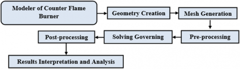
CFD simulation techniques are efficient tool for representing a mechanical problem and analyzing their physical phenomena for engineering applications. In the present simulation, the commercial CFD software ANSYS 17.0 FLUENT software with premixed flame-let model and the dynamics of premixed flame through counter vertical burner under influencing of magnetic field, Soldwork ver. 2019, are used to model and simulate the counter flame burner, three models at different conditions. There are several steps that carried out in order to perform the simulations, these steps are presented in Figure 1.
Figure 1. Simulation steps in ANSYS 17
The modelling is carried out in sold work and subsequently the mesh is imported FLUENT Premixed Flame-let Module for solving and post processing as combustion problem. This simulation is divided into three combustion models according to the research objectives. A benchmark comprehensive numerical model to simulate the counter flame burner under influencing magnetic field was developed to predict the Magneto-hydrodynamic behavior of the system. The solution procedure of the model was achieved by computational coding in ANSYS environment. And assumptions were; the flow steady, the simulation analyzed 1D, a uniform transverse magnetic field is applied normal to the flow direction, and it was assumed that both gases are treated as two interacting continua and densities of the mixtures remain constant.
2.2 Modeler for premixed double counter flame
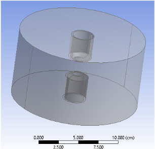
A three dimensional model of premixed gas fuel-air vertical counter burners are prepared in SolidWorks software. A computational fluid dynamics (CFD) model is used to investigate the premixed stationary flame under influence of magnetic field at different parameters, such as burning velocity, quenching diameter, stability limits, and dynamical premixed gas fuel/air flow. The initial step in CFD simulation is to prepare a computational domain. A three dimensional model of premixed gas fuel-air burner is prepared in SolidWorks software. The dimensions of premixed counter-flow burner geometry are taken from experimental setup and is shown in Table 1. The geometrical model of counter-flow burner is shown in Figure 2. The counter-flow burner system includes two counter tubes at 26 mm diameter, with each one has an end edge of 16 mm diameter, and the distance between burners edges was fixed on 30 mm. The air/LPG mixture is flowing through top and bottom a cross-sectional area of the burner’s edges. There are three schemes (Model-D1, Model-D2, and Model-D3) with different distance between magnetic poles 150mm, 180 mm, 220 mm are used.
Table 1. Dimensions for the counter flow burners geometry
|
Model-D1 |
|||
|
Inner dia. |
Outer dia. |
Distance between burners edges |
Distance between magnetic poles |
|
16 mm |
22 mm |
30 mm |
150 mm |
|
Model-D2 |
|||
|
16 mm |
22 mm |
30 mm |
180 mm |
|
Model-D3 |
|||
|
16 mm |
22 mm |
30 mm |
220 mm |
Figure 2. Computational domain prepared of three schemes of counter-flow burners
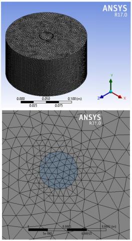
One of the important steps in CFD is to create the computational grid, which consists of computational cells. The governing equations are solved in computational cells. The air/LPG flow and combustion field domain are meshed with tetrahedral elements using unstructured meshing. The unstructured tetrahedral meshing is selected because of complex geometry. A recommended approach to eliminate the influence of mesh size is to seek the mesh independent solution has been followed. Optimum grid size is selected where solution is not affected by the grid size. Figure 3 shows the 3D meshed geometrical model of counter flame burner. The most accurate and comparable results for the counter flame front between the burner edges under influencing the magnetic field; burning velocity, quenching diameter and behavior of the flame stability were obtained by fine meshing scheme. Thus, the fine mesh was selected to perform the simulations and result interpretation. Nodes and elements of fine mesh for all schemes represented in Table 2. For all domains, number of cells in Table 2 selected for all simulation according to grid dependency as shown in Figure 4.
Figure 3. Geometrical mesh model of counter flame burner
Table 2. Nodes and elements for counter flame burners
|
Counter Burners |
Nodes |
Elements |
|
Model-D1 |
98341 |
589433 |
|
Model-D2 |
98893 |
591334 |
|
Model-D3 |
98987 |
594663 |
Figure 4. Cells selected for all simulation models
2.3 Governing equations
The solution technique follows the finite volume method to solve the system of governing partial differential equations by using ANSYS 17.0 Fluent FGMs Module. Transient numerical simulation for the laminar counter flow premixed flame is carried out using Premixed FGMs module [2, 3]. While the only possible configuration for a diffusion flame let in 1D is opposed flow, 1D steady premixed flame lets can have several configuration. These include unstrained adiabatic freely propagating, unstrained non-adiabatic burner-stabilized. As a strain opposed flow premixed flames. The 1D adiabatic premixed flame equations can be transformed from physical-space to reaction – progress space [5, 6]. Neglecting different-diffusion, these equations are:
$\rho \frac{\partial Y_k}{\partial t}+\frac{\partial Y_k}{\partial c} \dot{\omega}_c=\rho x_c \frac{\partial^2 Y_k}{\partial c^2}+\dot{\omega}_c$ (1)
$\begin{aligned} \rho \frac{\partial T}{\partial t}+\frac{\partial T}{\partial c} \dot{\omega}_c= & \rho x_c \frac{\partial^2 T}{\partial c^2}-\frac{1}{c p} \sum_k h_k \dot{\omega}_k +\frac{\rho x_c}{c p}\left(\frac{\partial c p}{\partial c}+\sum_k c p \cdot k \frac{\partial Y_k}{\partial c}\right) \frac{\partial T}{\partial c}\end{aligned}$ (2)
where, Yk is the Kth species mass fraction, T is the temperature, ρ is the fluid density, t is time, ὡk is the Kth species mass reaction rate, hk is the total enthalpy, and cpk is the Kth species specific heat at constant pressure. The scalar-dissipation rate, Xc in Eq. (1) and Eq. (2) is defined as:
$x_c=\frac{\lambda}{\rho c p}|\nabla c|^2$ (3)
where, λ is the thermal conductivity. Note that Xc varies with c and is an input to the equation set.
2.4 Initial and boundary conditions
The values of the input parameters, which are the fuel gas-air flow velocities, A/F percentage values, and magnetic field intensity, to diffusion and premixed flame-let cases, are obtained from the mixture measured data from the experimental test. Experimental parameters were measured at entry counter burner of all modeller’s schemes and modeller for fuel gas-air mixtures, as shown in Table 3.
Table 3. Simulation parameters and variables
|
Parameter |
Values |
|
Air flow rate |
40 – 93 SLPM |
|
LPG flow rate |
9 – 36 SLPM |
|
Distance between burners edges |
30 mm |
|
Distance between magnetic poles |
150, 180, and 220 mm |
|
Magnetic field intensity |
1000, 2000, 3000, 4000, and 5000 gauss |
Then, the numerical simulation has also been carried out for the same experimental parameters. Numerical simulation of all modellers were carried out successfully by results compared with experimental measurements. Further evaluation was achieved by applying considerable values of same parameters to study effect of increasing air-fuel gas ratio, magnetic intensity and combustion models types on burning velocity, flame stability limits. Moreover, changing distance between magnetic poles was carried out by using three values (150 mm, 180 mm, and 220 mm) when distance between burner edges is 30 mm, increased air-fuel gas ratio of the entry parameter was represented a new evaluation variable. Whilst output parameters connected to volume fraction distribution of flame front, burning velocity, temperature distribution.
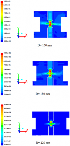
Figure 5 shows velocity contours for three models of counter burner at different distances between magnetic field poles 150, 180, and 220 mm with B = 5000 gauss, the effect of magnetic field on the diameter of flame disc and the brightness of the flame changed as a result of the increase in the rush of oxygen towards the combustion area due to the effect of the magnetic force.
When supply combustion zone with the negative gradient magnetic field, so back decreasing magnetic field, increases the supply of oxygen to the combustion region by inducing an oxygen flow to the vicinity of the flame front. Increase in oxygen flow provides more oxygen for the combustion leading to the promotion of chemical reaction, i.e., fuel and air react faster resulting in flame disc decrease (preventing the flame front from spreading to a wider range away from the burner edge, which leads to a decrease in the flame front diameter). On the other hand, the results showed that increasing the distance between magnetic poles reduces the effect of the magnetic field on the dimensions of the flame front, this behavior will lead to an increase in the flame front diameters and due to that will decreased burning.
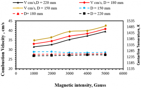
Figure 6 shows the effect of magnetic field on the combustion velocity and flame temperature in the combustion domain by applying magnetic field on the mid-distance between counter burner edges. For the mid-section (flame disc), the overall combustion velocity in the domain increased with increasing magnetic intensity due to the decreasing area of the flame disc. Regarding the temperature values as a result of magnetic field applied to the flame disc of the burner, while the velocity was increased in the center of the nozzle, the temperature was remained slow affected by increasing magnetic field. The reason is that the fuel flow developed in the burner pipe before it reached the edge exit. Conversely, when magnetic field was applied to the mid-section of the burner increasingly, the maximum flame temperature was declined slightly by approximately 40 degrees.
Figure 5. Velocity contours for three models of counter burner at different distances between magnetic field poles 150, 180, and 220 mm with B = 5000 gauss
Figure 6. Effect of magnetic field on combustion velocity and flame temperature in the counter burner
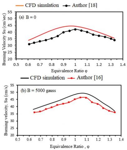
In Figure 7 the comparison between CFD simulation results and experimental measurements for Wu et al. [16] and Abdul Wahhab [18] of the burning velocity at a magnetic field intensity (B = 0 and 5000 gauss) shows a good agreement in the premixed combustion. The mean percentage of differences between, the CFD simulation of premixed flame and the experimental measurement for author [18] was 8.8% at B = 0, while the CFD simulation results and experimental measurements for author [16] of the burning velocity at a magnetic field intensity B = 5000 gauss, it can see a good agreement in the premixed was are 6.4%.
Figure 7. Validation of burning velocity at a magnetic intensity B = 0 and 5000 gauss
The mechanism for magnet–flame interaction is due to the magnetic para-magnetism of oxygen in the air, which is diffused into the flame. However, the combustion characteristics of the flame subject to the influence of magnetic field are not fully expansion yet. In this side some of questions must answering on it. First, which any parameter influencing on flame front is most sensitive to gradient magnetic field. Second, can flame temperature be varied by gradient magnetic field? This paper describes a numerical study of influence of magnetic field on premixed flame on the counter burner. Laminar premixed flames for different LPG gas flow rates propagating in counter burner of a different magnetic field intensities 1000 to 5000 gauss have been numerically investigated. An influence of the changing a distance between magnetic poles and magnetic force on the flame behavior, combustion velocity and flame temperature has been analyzed. The simulation was carried out using ANSYS Fluent software version 17.0, with premixed flame-let model and the dynamics of premixed flame through counter vertical burner under influencing of magnetic field. CFD results were appeared for behavior laminar flame in counter burner:
Further analysis of the influence of magnetic field on combustion characteristics for another gas fuel such as methane, propane to study effect number carbon atoms and knowing the extent of its effect on the stability limits. Also, study the effect of magnetic field on the propagation turbulent flame.
The authors are obliged to the University of Technology- Iraq for providing support through the Energy and Renewable Energies Technology Center.
[1] Torresi, M., Fornarelli, F., Fortunato, B., Camporeale, S., Saponaro, A. (2017). Assessment against experiments of devolatilization and char burnout models for the simulation of an aerodynamically staged swirled low-NOx pulverized coal burner. Energies, 10: 66. https://doi.org/10.3390/en10010066
[2] Senneca, O., Vorobiev, N., Wuetscher, A., Cerciello, F., Heuer, S., Wedler, C., Span, R., Schiemann, M., Muhler, M., Scherer, V. (2019). Assessment of combustion rates of coal chars for oxycombustion applications. Fuel, 238: 173-185. https://doi.org/10.1016/j.fuel.2018.10.063
[3] Abdul Wahhab, H.A., Aziz, A.A.R., Al-Kayiem, H.H., S Nasif, M. (2017). Mathematical modeling of the flow of diesel-CNG fuel mixture in a pipe under the influence of a magnetic field. Journal of Applied Fluid Mechanics, 10(1): 389-396. https://doi.org/10.18869/acadpub.jafm.73.238.26293
[4] Rajamanickam, P., Coenen, W., Sánchez, A.L., Williams, F.A. (2019). Influences of stoichiometry on steadily propagating triple flames in counterflows. Proceedings of the Combustion Institute, 37(2): 1971-1977. https://doi.org/10.1016/j.proci.2018.05.044
[5] Abdulwahhab, H.A., Aziz, A.R.A., Al-Kayiem, H.H., Nasif, M.S. (2017). Modeling of diesel-compressed natural gas bubbly flow under influencing of a magnetic field. Journal of Engineering Science and Technology, 12(7): 1930-1938.
[6] Charest, M.R., Gülder, Ö.L., Groth, C.P. (2014). Numerical and experimental study of soot formation in laminar diffusion flames burning simulated biogas fuels at elevated pressures. Combustion and Flame, 161(10): 2678-2691. https://doi.org/10.1016/j.combustflame.2014.04.012
[7] El-Adawy, M., Abdul-Wahhab, H.A., Aziz, A.R.A., Opatola, R.A., Ismael, M.A., Al-Kayiem, H.H. (2023). Magneto-Hydrodynamic effects on Diesel/CNG bubbly flow enhanced by Fe3O4 Nanoparticles: Experimental and mathematical assessments. Alexandria Engineering Journal, 62: 415-429. https://doi.org/10.1016/j.aej.2022.07.042
[8] Wehrfritz, A., Kaario, O., Vuorinen, V., Somers, B. (2016). Large eddy simulation of n-dodecane spray flames using flamelet generated manifolds. Combustion and Flame, 167: 113-131. https://doi.org/10.1016/j.combustflame.2016.02.019
[9] Wahhab, H.A.A., Aziz, A.R.A., Al-Kayiem, H.H., Nasif, M.S., El-Adawy, M. (2018). Magneto-hydrodynamics of bubbly flow in horizontal pipe: New criteria through numerical simulation. In AIP Conference Proceedings, Kuala Lumpur, Malaysia, pp. 1-24. https://doi.org/10.1063/1.5075592
[10] Donini, A., Bastiaans, R., van Oijen, J., de Goey, L. (2017). A 5-D implementation of fgm for the large eddy simulation of a stratified swirled flame with heat loss in a gas turbine combustor. Flow, Turbulence and Combustion, 98(3): 887-922. https://doi.org/10.1007/s10494-016-9762-x
[11] Hu, E., Huang, Z., He, J., Jin, C., Zheng, J. (2009). Experimental and numerical study on laminar burning characteristics of premixed methane–hydrogen–air flames. International Journal of Hydrogen Energy, 34(11): 4876-4888. https://doi.org/10.1016/j.ijhydene.2009.03.058
[12] Zimont, V.L., Biagioli, F., Syed, K. (2001). Modelling turbulent premixed combustion in the intermediate steady propagation regime. Progress in Computational Fluid Dynamics, An International Journal, 1(1-3): 14-28. https://doi.org/10.1504/PCFD.2001.001467
[13] Van Oijen, J.A., Lammers, F.A., De Goey, L.P.H. (2001). Modeling of complex premixed burner systems by using flamelet-generated manifolds. Combustion and Flame, 127(3): 2124-2134. https://doi.org/10.1016/S0010-2180(01)00326-6
[14] Mola, A.H., Abdul Wahhab, H.A., Naji, Z.H. (2023). Effects of nozzle diameter and number of carbon atoms in fuel on flame quenching in counter burner. In ICPER, Korea, pp. 123-131. https://doi.org/10.1007/978-981-19-1939-8_11
[15] Van Oijen, J.A., Donini, A., Bastiaans, R.J.M., ten Thije Boonkkamp, J.H.M., De Goey, L.P.H. (2016). State-of-the-art in premixed combustion modeling using flamelet generated manifolds. Progress in Energy and Combustion Science, 57: 30-74. https://doi.org/10.1016/j.pecs.2016.07.001
[16] Wu, W.F., Qu, J., Zhang, K., Chen, W.P., Li, B.W. (2016). Experimental studies of magnetic effect on methane laminar combustion characteristics. Combustion Science and Technology, 188(3): 472-480. https://doi.org/ 10.1080/00102202.2015.1119825
[17] Sankar, V., Chandran, S.M., Tomy, T., Raj, U., Samson, V., Ramachandran, K. (2018). Effect of magnetic field to reduce emissions and improve combustion performance in a spark-ignition engine. In Advanced Manufacturing and Materials Science: Selected Extended Papers of ICAMMS 2018, Guiyang, China, pp. 1-10. https://doi.org/10.1007/978-3-319-76276-0_1
[18] Abdul Wahhab, H.A. (2020). Investigation of stability limits of a premixed counter flame. International Journal of Automotive and Mechanical Engineering, 18(1), 8540-8549. https://doi.org/10.15282/ijame.18.1.2021.13.0648
[19] Zamashchikov, V.V. (2004). Some features of gas-flame propagation in narrow tubes. Combustion, Explosion, and Shock Waves, 40(5): 545-552. https://doi.org/10.1023/B:CESW.0000041406.83951.ca
[20] Maruta, K., Kataoka, T., Kim, N.I., Minaev, S., Fursenko, R. (2005). Characteristics of combustion in narrow channel with a temperature gradient. Proceedings of the Combustion Institute, 30: 2429-2436. https://doi.org/10.1016/j.proci.2004.08.245
[21] Lockett, R.D., Boulanger, B., Harding, S.C., Greenhalgh, D.A. (1999). The structure and stability of the laminar counter-flow partially premixed methane/air triple flame. Combustion and Flame, 119(1-2): 109-120. https://doi.org/10.1016/S0010-2180(99)00046-2
[22] Agarwal, S., Kumar, V., Shakher, C. (2018). Temperature measurement of wick stabilized micro diffusion flame under the influence of magnetic field using digital holographic interferometry. Optics and Lasers in Engineering, 102: 161-169. https://doi.org/10.1016/j.optlaseng.2017.10.019
[23] Sirignano, W.A. (2021). Combustion with multiple flames under high strain rates. Combustion Science and Technology, 193(7): 1173-1202. https://doi.org/10.1080/00102202.2019.1685507
[24] Perdana, D. (2023). The experimental of impact of additional magnetic fields and nitrogen pressure on olive oil droplet combustion. Indonesian Journal of Applied Research, 4(1): 1-10. https://doi.org/10.30997/ijar.v4i1.280
[25] Oommen, L.P., Kumar, G.N. (2020). Influence of magneto-combustion on regulated emissions of an automotive engine under variable speed operation. International Journal of Vehicle Structures and Systems, 12(1): 109-112. https://doi.org/10.4273/ijvss.12.1.25