Liang Li* | Chen Zhao | Chunlei Li | Shaojun Qin
OPEN ACCESS
The end position of industrial robots cannot be measured directly. To solve the problem, this paper proposes an end position detection method for industrial robots based on laser tracker. First, the target ball was fixed onto the end flange of a six degree-of-freedom (DOF) industrial robot by the laser target. Then, the conversion between different coordinate systems was obtained through two experiments. In the first experiment, the end of the robot rotated about the axes of the robot tool coordinate system (RTCS). The second experiment is about the single-joint rotation of the robot. Based on the conversion relationship, the author computed the deviation of the end position read on the robot controller from the position that the end actually arrives at. Experimental results show that the proposed method is feasible for online detection of the end position for industrial robots. The research lays the basis for calibrating geometric parameters of industrial robots, and provides a guide on improving the positioning accuracy of industrial robots.
industrial robots, identification accuracy, position detection, coordinate conversion, laser target
Industrial robot is a highly integrated product of mechatronics. This a high value-added technical product enjoys a wide scope of application, setting a benchmark for industrial automation and Industry 4.0 [1]. In recent years, domestic industrial robots have been applied in more and more scenarios. Good repeatability alone can no longer satisfy the growing demand. The development of domestic industrial robots is mainly bottlenecked by their relatively low identification accuracy of position. This is an urgent problem to be solve by domestic manufacturers of industrial robots [2].
There are many ways to detect the end position of industrial robots. The common approaches are based on one of the following tools: cable, vision, coordinate-measuring machine (CMM), laser tracker, ball bar, pull-wire sensor, and acoustic sensor [3-5]. For example, Dynalog (US) developed a cable-based robot calibration system. Guo and Lv [6] suggested measuring the end position of industrial robots by active vision. Zhuang and Roth [7] measured the robot attitude based on images. Tang et al. [8] designed a CMM-based detection method for attitude precision of robots. Ren et al. [9-10] calibrated robots with a laser tracker. Muelaner et al. [11] used laser tracker to measure the repeatability of KUKA KR 240 tandem robot. Ren et al. [12] proposed a universal attitude detection method for industrial robots. Most of the above detection methods can only achieve a low accuracy in a small range, failing to realize real-time online measurement. The only strategies that immune to these defects are based on laser tracker. This instrument has been extensively applied, because it can accurately capture various real-time spatial motions in a large scope in a stable and robust manner [13-14]. Many have adopted laser tracker to identify the end position of industrial robots.
To measure the end position of a robot with laser tracker, two conversion relationships should be given special attention: that between the robot coordinate system (RCS) and laser tracker measurement coordinate system (LTMCS), and that between the center of laser target ball (ball center) and the tool center point (TCP) at the end of robot. Many scholars have explored these two relationships. For instance, Liu et al. [15] set up a homogeneous transformation model, analyzed the source of conversion errors between coordinate systems, and developed a random sample consensus (RANSAC) algorithm for rapid conversion based on least squares (LS) method. Xiang et al. [16] computed the ball center identification accuracy RCS under distance constraint, and converted the coordinates through the LS iteration of Rodrigues' rotation matrix. These two methods pose high requirements on mathematical foundation and need to construct multiple mathematical models. Zhang et al. [17] obtained a rotation matrix through single-joint rotation experiment on a robot, derived the conversion relationship between the ball center and the TCP from the end trajectory in joint rotation, and then calculated the translation vector based on the relationship. The problem with this approach is the huge computing load. To solve the problems with existing methods, this paper proposes an end position detection method for industrial robots based on laser tracker [18]. The conversion relationship between ball center and the TCP was measured through experiment, reducing the computing load in the conversion between coordinate systems. The proposed method can realize real-time online measurement of the end position of industrial robots.
The remainder of this paper is organized as follows: Section 2 explains the principle of our detection method for end position of industrial robots; Sections 3 obtains the conversion relationship between ball center and the TCP; Section 4 derives the rotation matrix and translation laser tracker working coordinate system (LTWCS); Section 5 verifies the effectiveness of our method through an experiment; Section 6 puts forward the conclusions.
The research object is a six degree-of-freedom (DOF) industrial robot. A target ball was fixed onto the end of the robot by a laser target, and the end position was measured by a laser tracker. The objective is to compare the deviation of the position read from the robot controller and the actual position the end arrives at.
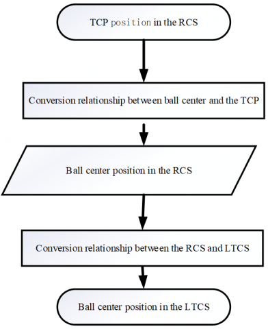
As shown in Figure 1, our experiment was carried out in two steps. In the first step, the TCP position in the RCS was read from the robot controller, and then converted to the position of ball center in the RCS, according to the conversion relationship between ball center and the TCP.
In the second step, the position of ball center was converted to a position in the LTMCS, according to the conversion relationship between the RCS and the LTMCS. The converted position was compared with the ball center position measured by the laser tracker, yielding the deviation.
Figure 1. Workflow of the experiment
To monitor the changes in end position of the industrial robot, the target ball was fixed onto the end flange of the robot with a laser target. The fixing of the target ball and the laser target is explained in Figure 2. Then, the target ball, the laser target and the end of the robot were viewed as a rigid body in space. The spatial motion of the rigid body could be identified based on the changes in ball center position.
In general, the data read on the robot controller is the position of the TCP in the RCS, while the ball center position lies in the LTCS. Therefore, the TCP position in the RCS should be converted to the ball center position in the RCS.
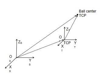
First, laser tracker working coordinate system (LTWCS) OTXTYTZT was created in Spatial Analyzer (SA), in which the origin coincides with the TCP and the axes point to the same directions with those in the RCS OBXBYBZB. Then, a rotation matrix R1 could be obtained between the two coordinate systems (Figure 3). When all the joints of the robot returned to the original positions, the TCP position $T_{0}^{B}$ in the RCS was read, and the ball center position $P_{S}^{T}$ in the LTWCS was measured at the same time. Then, the ball center position $P_{S}^{B}$ in the RCS can be obtained by:
${{P}_{S}}^{B}={{R}_{1}}\cdot {{P}_{S}}^{T}+T{{{}_{0}}^{B}}$ (1)
Figure 2. The fixing of the target ball and the laser target
Figure 3. Conversion of ball center position
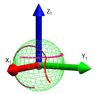
Next, the end of the robot rotated about each of the three axes in the tool coordinate system (RTCS). During the rotation, the ball center position was measured at equal intervals, creating three sets of measured points. All the measured points were fitted into a sphere on the SA, and the ball center is the TCP. Taking the TCP as the origin, a LTWCS was established whose axes are parallel to and pointing to the same directions as those of RCS (Figure 4).
Figure 4. The WCS
After that, all the joints of the robot returned to the original positions. Then, the coordinates of the ball center in the LTWCS were measured as $P_{S}^{T}=[\Delta X, \Delta Y, \Delta Z]^{T}$ , and the TCP position $T_{0}^{B}$ in the RCS was read.
Because the axes of the robot and working coodinate systems point to the same directions, the following rotation matrix can be established:
$R_{2}=\left[\begin{array}{lll}{1} & {0} & {0} \\ {0} & {1} & {0} \\ {0} & {0} & {1}\end{array}\right]$
Hence, the ball center position in the LTWCS can be obtained as $P_{S}^{T}=[63.294,73.8927,41.3204]^{T}$; The TCP position read in the RCS can be written as $T_{0}^{B}=[482.015,0.005,743.964]^{\mathrm{T}}$. Substituting the two values in formula (1), the ball center position in RCS can be computed as $P_{S}^{B}=\left[\begin{array}{lll}{54} & {5} & {309}\end{array}, 73.8977,785.2844\right]^{\mathrm{T}}$.
Based on the conversion relationship between ball center and the TCP in Section 3, the TCP position read on the robot controller in the RCS can be converted to the ball center position in that system. Meanwhile, the ball center position was actually measured in the LTMCS. Thus, the conversion relationship between the RCS and the LTMCS should be obtained, before identifying the deviation of the position read from the robot controller and the actual position the end arrives at.
Figure 5 shows the experiment system model. On the left is the laser tracker, which can track the ball center position in real time, and the OMXMYMZM is the laser tracker fixed measurement coordinate system (LTMCS). On the right is a domestic 6 degree-of-freedom (DOF) industrial robot, with a target ball on its end flange, and OBXBYBZB is the RCS.
Figure 5. Model of the experiment system
The conversion relationship between the two coordinate system consists of a rotation matrix and a translation vector. The rotation matrix was obtained through single joint rotation of the robot. The ball center trajectories of the single joint rotation were processed in the SA, revealing the geometric relationship between the trajectories. Then, the translation vector could be derived from the conversion relationship between ball center and the TCP obtained in Section 3. Then, the conversion relationship between the RCS and the LTMCS can be obtained as:
${{P}^{M}}={{R}_{2}}\cdot {{P}^{B}}+T$ (2)
where, PB and PM are the coordinates of a point P in space under the RCS and the LTMCS, respectively; R2 is the rotation matrix; T is the translation vector. By formula (2), the ball center position read in the RCS could be converted to the LTMCS.
Next, all the joints of the robot returned to the original positions. The three joints parallel to the three axes of the RCS were selected, namely, Axis 1 parallel to OBZB, Axis 3 parallel to OBYB and Axis 4 parallel to OBXB.
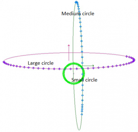
Axes 1, 3 and 4 started to rotate in turn from the original position of the robot, and the ball center was measured at equal intervals through the rotation process. In this way, three sets of measuring points were obtained. Each set of points was fitted into a circle in the SA. The three resulting circles are denoted as large circle, medium circle and small circle, respectively. Their unit normal vectors are respectively denoted as nx, ny and nz. Then, the rotation matrix between the RCS and the LTMCS can be obtained as R2=[nx ny nz].
Figure 6 presents the circles fitted in the experiment. The rotation matrix between the RCS and the LTMCS was obtained as:
Figure 6. The fitting circles
The ball center position in the LTWCS can be expressed as $P_{S}^{T}$=[ΔX, ΔY, ΔZ]T=[63.294, 73.8972, 41.3204]T.
Drawing on the previous research [17], the following equation can be derived:
$\overrightarrow{{{O}_{X}}{{O}_{B}}}={{\left[ -\sqrt{{{R}_{D}}^{2}-\Delta {{Y}^{2}}},-{{Y}_{D}},-{{Z}_{D}} \right]}^{T}}$ (3)
$T={{O}_{B}}^{M}={{O}_{X}}^{M}+{{R}_{2}}\cdot \overrightarrow{{{O}_{X}}{{O}_{B}}}$ (4)
where, $\overrightarrow{O_{X} O_{B}}$ is the vector in the RCS; $O_{B}^{M}$ are the coordinates of the origin of the RCS in the LTMCS; $O_{X}^{M}$ are the coordinates of the center of the small circle in the LTMCS; $R_{D}$ is the radius of the large circle.
The radius of the large circle can be fitted as RD=547.8042 mm. According to formulas (3) and (4), the translation vector can be obtained as T=[2963.0668, -3180.8709, -497.3839]T.
For industrial robots, the position read on the robot controller may deviate from the actual position the end arrives at. The deviation may arise from factors like poor controller resolution, low reading accuracy of joint encoder, assembly misalignment and installation error. This section experimentally verifies the obtained conversion relationships between the ball center and the TCP and between the RCS and the LTCS, and measures the end position deviation of an industrial robot in the lab.
Ten measuring points were randomly selected from the workspace of the robot. Then, a program was prepared for the robot to move from the original position to the destinations, i.e. the measuring points. The program was executed manually, such that the robot moves along each trajectory three times. Once the robot arrived at a destination, the TCP position in the RCS was recorded immediately, and converted twice to obtain the ball center position in the LTCS (Figure 7). Then, the obtained position was compared with the ball center position measured by the laser tracker, outputting the deviation of end position.
Figure 7. Workflow of position conversions
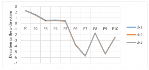
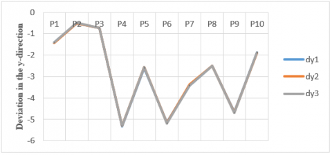
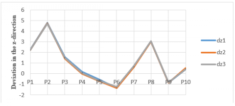
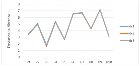
The collected data were processed and analyzed, creating the deviation curves between the read and measured ball center positions. The deviations in x-, y- and z- directions and the deviation of distance are shown in Figures 8-11, respectively.
As shown in above figures, the maximum absolute deviations in the x-, y- and z-directions were 5.7627 mm, 5.3256 mm and 4.7920 mm, respectively; the overall maximum absolute deviation in the three directions was 7.180mm. The relatively large deviation may come from the following factors: the target industrial robot has a large assembly clearance after repeated removals and installations, the surface of the workbench is not level, the robot has a poor positioning accuracy due to long-term mechanical wear, and some errors are induced by the conversions between coordinate systems.
Figure 8. Deviation in the x-direction
Figure 9. Deviation in the y-direction
Figure 10. Deviation in the z-direction
Figure 11. Deviation in distance
The domestic industrial robots generally have a low positioning accuracy. What is worse, the robot industry is in want of feasible standards and detection instruments. This paper solves the defects of the existing conversion methods between the RCS and the LTCS, and then designs an end position detection method for industrial robots based on laser tracker. The method is simple to operate and widely applicable, eliminating the need for advanced measuring instruments or technical plans. The industrial robots whose positioning accuracy has been reduced through long-term wear could be effectively monitored by our method. Of course, our method also faces some limitations, namely, the relatively high measuring deviation and the complex data analysis. These limitations will be solved through error compensation in future research.
This paper is supported by Key Research and Development Plan of Shaanxi Province, China (Grant No.: 2019GY-091), and Key Innovative Research Projects for Graduate Students, Baoji University of Arts and Sciences (Grant No.: YJSCX18ZD05).
[1] Pogliani, M., Quarta, D., Polino, M., Vittone, M., Maggi, F., Zanero, S. (2019). Security of controlled manufacturing systems in the connected factory: The case of industrial robots. Journal of Computer Virology and Hacking Techniques, 15(3): 161-175. https://doi.org/10.1007/s11416-019-00329-8
[2] Colim, A., Costa, S., Cardoso, A., Arezes, P., Silva, C. (2019). Robots and human interaction in a furniture manufacturing industry-Risk assessment. In International Conference on Applied Human Factors and Ergonomics, 969: 81-90. https://doi.org/10.1007/978-3-030-20497-6_8
[3] Hong, Z.Y., Mei, J.P., Zhao, X.M., Huang, T. (2007). Kinematic calibration of the parallel mechanical using double-ball-bar system. Chinese Journal of Mechanical Engineering, 43(7): 16-22. http://dx.doi.org/10.3321/j.issn:0577-6686.2007.07.004
[4] Knoll, A., Kovacs, P. (2003). Method and device for the improvement of the pose accuracy of effectors on mechanisms and for the measurement of objects in a workspace. United States Patent, 6529852: 1-10.
[5] He, L.L., Zhu, J.K. (2004). A new method for measuring the position and orientation of parallel platform. Machine Tool & Hydraulics, (11): 183-184. http://dx.doi.org/10.3969/j.issn.1001-3881.2004.11.074
[6] Guo, J. Y., Lv, T.S. (2003). Active end vision based robot attitude measurement. Journal of Shanghai Jiaotong University, 37(5): 715-719.
[7] Zhuang, H., Roth, Z. S. (2018). Camera-Aided Robot Calibration. CRC Press. https://doi.org/10.1201/9781315138725
[8] Tang, Y.C., Li, J.Z, Lin, A.D., Kuang, S.L. (2019). Robot pose accuracy detection method based on coordinate measuring machine. Computer Engineering and Applications, 11: 2127.
[9] Ren, Y.J., Zhu, J.G., Yang, X.Y., Ye, S.H. (2007). Method of robot calibration based on laser tracker. Journal of Mechanical Engineering, 43(9): 196-200. http://dx.doi.org/10.3321/j.issn:0577-6686.2007.09.038
[10] Ren, Y., Zhang, F., Guo, Z.M., Song, Z.Q., Gong, T. (2018). A general pose testing method of industrial robot. Acta Metrologica Sinica, 39(5): 616-621. http://dx.doi.org/10.3969/j.issn.1000-1158.2018.05.05
[11] Muelaner, J.E., Wang, Z., Maropoulos, P.G. (2011). Concepts for and analysis of a high accuracy and high capacity (HAHC) aerospace robot. Proceedings of the Institution of Mechanical Engineers, Part B: Journal of Engineering Manufacture, 225(8): 1393-1399. https://doi.org/10.1177%2F0954405411406939
[12] Ren, Y.J., Yin, S., Zhu, J. (2012). Calibration technology in application of robot-laser scanning system. Optical Engineering, 51(11): 114204. https://doi.org/10.1117/1.OE.51.11.114204
[13] Li, R., Qu, X.H. (2014). The error feature analysis and positioning compensation technology for robot motion based on combined measurement. Robot, 36(3): 279-284. http://dx.doi.org/10.3724/SP.J.1218.2014.00279
[14] Nubiola, A., Bonev, I.A. (2013). Absolute calibration of an ABB IRB 1600 robot using a laser tracker. Robotics and Computer-Integrated Manufacturing, 29(1): 236-245. https://doi.org/10.1016/j.rcim.2012.06.004
[15] Liu, Z.J., Wang, H., Chen, X., Xia, Y.X., Du, Z.F., Li, Y.S., Lin, J.P. (2017). Study on the method of coordinate transformation between robot and laser tracker. China Measurement & Testing Technology, 43(11): 102-107. http://dx.doi.org/10.11857/j.issn.1674-5124.2017.11.020
[16] Xiang, M.Z., Fan, B.X., Li, X.Y., Long, C.Y. (2018). Study on coordinate transformation between a laser tracker and a robot. Aeronautical Manufacturing Technology, 61(1): 98-101. http://dx.doi.org/10.16080/j.issn1671-833x.2018.01/02.098
[17] Zhang, B., Wei, Z.Z., Zhang, G.J. (2010). Rapid coordinate transformation between a robot and a laser tracker. Chinese Journal of Scientific Instrument, 31(9): 1986-1990.
[18] Huang, K., He, C.S, Zhen, S.C., Hong, J., Zhao, F.M. (2016). An absolute positioning accuracy analysis method for robot based on interval analysis. China Mechanical Engineering, 27(11): 1467-1473. http://dx.doi.org/10.3969/j.issn.1004-132X.2016.11.009