OPEN ACCESS
Voltage control for multiple feeders has been controlled by single voltage regulator. But optimal voltage regulator for multiple feeders has disadvantage i.e. it is not suitable for all loading conditions. To overcome these problems we need to add one more voltage regulator otherwise connect a DG at that feeder. In this paper necessity of DG is proposed when one voltage regulator is not sufficient to control voltage for multiple feeders. The proposed scheme is depending upon the solution of linear integer programming method. One voltage regulator is sufficient under constrained loading conditions but when there is no solution then we need an extra voltage regulator to control the voltage profile of the network. For that purpose, connect DG to the feeders to enable good voltage profile. The main advantage of this scheme is only one voltage regulator is enough to control the voltage for any loading condition by adjusting the DG output. And also, we can summarize the max loading limit on that particular feeder. The results are shown to validate the proposed scheme.
distribution generation (DG), voltage control, distribution system, integer programming
The main task for the electrical utilities is to supply satisfactory voltage levels to consumers. Voltage regulator is a device which regulates voltage profile according to the reference value of the regulating point. Voltage regulator is nothing but an auto transformer having tapings which is nearly close to reference value. The combination of line drop compensator with voltage regulator is already well established and in use for some times now (Gonen, 2007). To reduce loss as well as to improve the voltage profile of the system, research is going on optimal location and optimal tap position (Choi and Kim, 2001; Choi and Kim, 2001).
Also, distribution network changing rapidly in day to day life, like increasing load demand, reliability concerns and need to reduce the CO2 emission. Now a day’s installation of DG in distribution network is increasing. While integrating DG with distribution network possess some new technical challenges and lot of benefits when it is integrating with distribution network (Ackermann et al., 2001; Pepermans et al., 2005). The limit of DG output is depending upon factors like thermal capacity, systems fault, protection issues, distribution system reverse power flow capabilities, and steady state voltage rise problem (Liewand and Strbac, 2002).
Hence by use of DG connected feeders there is no need of extra voltage regulator which reduces complexity. DG output is adjusted to that which the load on that feeder must be less than the allowable loading conditions.
The LDC having problem when DG is installed in the system, it will not work properly with the voltage regulator because LDC estimate voltage drop at the regulating point depending upon the local measurements. It does not consider the power injection at the regulating point by DG. For proper operation of voltage regulator when DG is installed, coordinated voltage schemes (or) active management schemes were proposed in literature.
The problem is considered as an optimization problem and according to the defined solution; the tap setting of voltage regulator is decided. The problem for optimal controlling of voltage regulator is that one voltage regulator is not sufficient for all loading conditions. Under some loading conditions, solution of the linear integer programming is not valid hence there is a tendency to control the voltage with extra voltage regulator. This is an extra complexity in the circuit as well as there is a need to solve the optimization problem again.
In this paper, we propose necessity of DG for optimal control of voltage regulator for multiple feeders. First, we take some constrained loading conditions and check whether there is solution or not. The problem is taken as optimization problem and the solution of that problem tells optimal tap setting of voltage regulator (Elkhatib et al., 2010). Solution gives integer number of tap settings required for optimal control of voltage. According to that voltage regulator set the voltage levels. If condition for feasible solution is not satisfied then there is a need of DG operation in that system. Now connect DG at that feeder which violates feasible solution. Forming voltage control problem as centralized optimization problem in the presence of DG was proposed (Elkhatib et al., 2011).
Voltage of the regulating point is increased when DG injects power at that point. Below equations represents that effect.
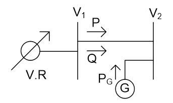
Consider a part of the system as shown in Figure 1 having DG at their load bus. The power injected by DG is PG. P is active power flow from source to load and Q is reactive power flow from source to load.
Figure 1. Part of the system having DG on load side
The voltage drop V1-V2 is expressed as
$\mathrm { V } _ { 1 } - \mathrm { V } _ { 2 } = \frac { \mathrm { PR } + \mathrm { Q } \mathrm { X } } { \mathrm { V } _ { 2 } }$ (1)
In P.U the above equation can be approximated as
$\mathrm { V } _ { 1 } - \mathrm { V } _ { 2 } = \mathrm { PR } + \mathrm { Q } \mathrm { X }$ (2)
Now Pg be power injected by DG into the system then above equation become
$\mathrm { V } _ { 1 } - \mathrm { V } _ { 2 } = \left( \mathrm { P } - \mathrm { P } _ { \mathrm { G } } \right) \mathrm { R } + \mathrm { Q } \mathrm { X }$ (3)
Output power of the DG increases i.e. PG then (P-PG) term will decrease hence voltage drop V1-V2 will decrease.
But if PG is greater than P then the term P-PG will negative results V2 is greater than V1. From this it is clear that the voltage at the regulating point is depending upon DG output power. This voltage rise problem can be solved efficiently then we can use feeder up to its thermal capability.
The current in the feeder limits DG capacity which is installed on any feeder to the level that will not cause violation for voltage profile. The voltage profile of the system is studied to know what amount of DG output will allow in the system, such as Min load, Max DG output and Max load, max DG output.
The voltage of different feeders has different loading conditions at different points is controlled by voltage regulator. The operation of voltage regulator is studied in this section.
3.1. Statement of the problem
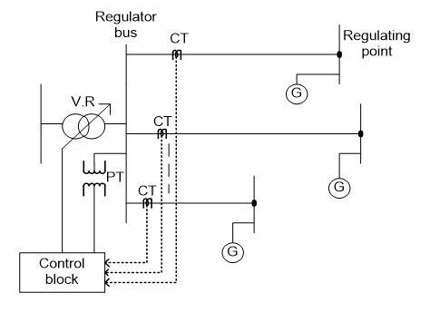
Consider a system having multiple feeders with various lengths, loading conditions and various types of feeders. For proper tap position of voltage regulator control block is used in the Figure 2 for achieving the following objectives.
Figure 2. The system under study
(1) Maintain voltage of the regulating point nearer to reference value. If it is not possible then at least maintain given range for that feeder.
(2) Regulator bus permissible voltage range should not be violating when achieving (1).
(3) Voltage regulator no of steps should be in between available range when achieving (1).
3.2. Summarization of optimization problem
$\operatorname { Min } _ { T } \sum _ { n = 1 } ^ { N } \left( \mathrm { V } _ { \mathrm { reg } } - \left( \mathrm { V } _ { \mathrm { ref } } ^ { \mathrm { n } } + \mathrm { k } _ { \mathrm { n } } \mathrm { l } _ { \mathrm { n } } \mathrm { S } _ { \mathrm { n } } \frac { \mathrm { L } _ { \mathrm { n } } } { 2 } \right) \right) ^ { 2 }$ (4)
Sub to
$\max _ { n } \left( V _ { \min } ^ { n } + k _ { n } l _ { n } S _ { n } \frac { L _ { n } } { 2 } \right) \leq V _ { r e g } \leq \min _ { n } \left( V _ { \max } ^ { n } + k _ { n } l _ { n } S _ { n } \frac { L _ { n } } { 2 } \right)$ (5)
$\frac { \max _ { n } \left( V _ { \min } ^ { n } + k _ { n } l _ { n } S _ { n } \frac { L _ { n } } { 2 } \right) - V _ { i n } } { V _ { t a p } } \leq T \leq \frac { \min _ { n } \left( V _ { \max } ^ { n } + k _ { n } l _ { n } s _ { n } \frac { L _ { n } } { 2 } \right) - V _ { i n } } { V _ { t a p } }$ (6)
$T _ { \min } \leq T \leq T _ { \max }$ (7)
$V _ { r e g } = V _ { i n } + T * V _ { t a p }$ (8)
$T _ { \max } = \frac { v _ { r e g } ^ { \max } - V _ { i n } } { V _ { t a p } } , T _ { \min } = \frac { v _ { r e g } ^ { \min } - V _ { i n } } { V _ { t a p } }$
Where,
$V _ { r e g }$→Output voltage of regulator
$V _ { r e f } ^ { n }$→nth feeder reference voltage
kn→nth feeder K – factor (p.uvd / KVA. miles)
ln→nth feeder loading factor.
Sn→rated load of the feeder n.
Ln→Length between regulator & nth feeder regulating point.
N→no. of feeders
Vin→input voltage to regulator.
T→tap position of the regulator
Vtap→One tap step corresponding voltage.
Tmin→Min integer number of voltage regulator that does not exceed the voltage regulator bus range.
Tmax→Max integer number of voltage regulator that does not exceed the voltage regulator bus range.
$V _ { r e g } ^ { \min }$→Min acceptable voltage of regulator bus.
$V _ { r e g } ^ { \max }$→Max acceptable voltage of regulator bus.
The term $k _ { n } l _ { n } S _ { n } \frac { L _ { n } } { 2 }$ is nothing but voltage drop of feeder n having length Ln with uniform distributed load of LnSn having k-factor of kn by using integer programming solvers like branch and bound method we solve the above optimization problem.
The optimal tap setting can be chosen as:
Let $a = \frac { V _ { r e g } ^ { o p t i m u m } - V _ { i n } } { V _ { t a p } }$, then
$T _ { o p t i m u m } = \left\{ \begin{array} { c } { r \text {ound} ( a ) \text { if } T _ { \min } \leq \operatorname { round } ( a ) \leq T _ { \max } } \\ { \text {ceil} ( a ) \quad \text { if } \quad \operatorname { round } ( a ) \leq T _ { \min } } \\ { \text {floor} ( a ) \text { if } T _ { \max } \leq \operatorname { round } ( a ) } \end{array} \right.$
Consider T should be integer and it is greater than zero.
Then feasible condition for getting solution of optimization problem is
$\operatorname { ciel } \left( \frac { \max _ { n } \left( V _ { \min } ^ { n } + k _ { n } l _ { n } S _ { n } \frac { L _ { n } } { 2 } \right) - V _ { i n } } { V _ { t a p } } \right) \leq f \operatorname { loor } \left( \frac { \min _ { n } \left( V _ { \max } ^ { n } + k _ { n } l _ { n } S _ { n } \frac { L _ { n } } { 2 } \right) - V _ { i n } } { V _ { t a p } } \right)$
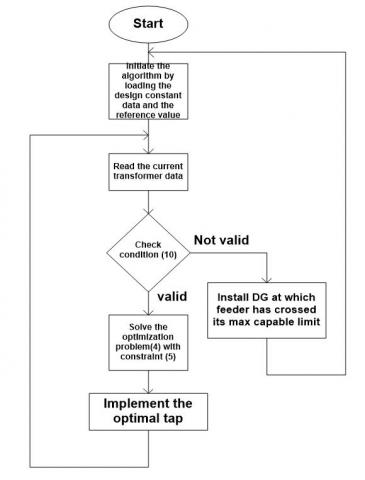
Figure 3. Recommended method
If feasible condition is not satisfied then there is no solution so we looking for extra voltage regulator otherwise we connect a DG for controlling of voltage by injecting the active power to the system.
In this section, we check the feasible condition for different loading condition of the feeder and determine the max load on the feeder which controlled by only one regulator. Different cases are studied without DG operations well as with DG.
Following assumptions are made to validate the proposed scheme
The regulator input voltage=1.01 p.u.
Regulating point max voltage=1.05 p.u.
Regulating point min voltage = 0.95 p.u.
Total no of taps=32
Tap ratio=0.003125 p.u.
|
|
Feeder 1 |
Feeder 2 |
Feeder 3 |
Feeder 4 |
|
Load KVA |
4500 |
5000 |
6000 |
4000 |
|
Length of feeder |
8 mi |
10 mi |
6 mi |
9 mi |
|
K-factor of feeder |
3.88e-6 |
3.88e-6 |
3.88e-6 |
3.88e-6 |
|
Ref. voltage |
0.95 |
0.96 |
0.97 |
0.95 |
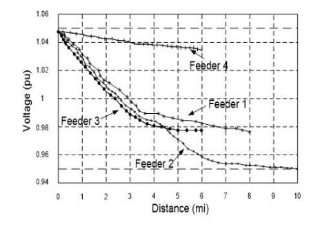
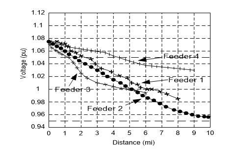
Case 1: Take above tabled values and check feasible condition. If the condition is satisfied then increase the load on feeder 1. Now take the load on feeder 1 is 9000 KVA. Again, check feasible condition if it is satisfying then again increase the load on feeder 1. Now load on feeder is 10700 KVA. Check condition (10) at this load also the condition for feasible solution is satisfied but beyond increase 10700 KVA there is no feasible solution because it violates the condition. Hence that load is max load for that feeder for operating only one voltage regulator when remaining loads are kept constant. The voltage profile of the feeders when we take the values as mentioned in the table is as shown in Figure 4.
Figure 4. Voltage profile for tabled values
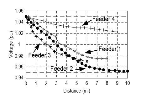
After increasing load on the feeder 1 the voltage of four feeders get effected so that it violets the max and min range of voltage regulator. The voltage profile for this condition is as shown in Figure 5.
Figure 5. Voltage profile when feeder exceeds their capability
Figure 6. voltage profile when DG is connected.
Case 2: Now again take above tabled values already it is proved that at that values condition is satisfied. Now increase the load on second feeder to 8560 KVA. Check whether condition is satisfying or not. At this load condition is satisfied but further increase in load the feasible condition violets so this is max load that it can capable but in this case also the min load of all four feeders must kept constant.
Case 3: In this case, the load on feeder 3 is increased to 14260 KVA. Condition 10 gets satisfied but further increase in load violets the condition without change the min load of four feeders.
Case 4: now increase the load on feeder 4 up to 9510 KVA beyond this load the feasible condition violets so this is max load that we can load on the feeder to strict only one voltage regulator.
Case 5: For simplicity take pure resistive load. Power factor for pure resistive load is unity. As mentioned in case 1 the max load that we can load on that feeder is 10700 KVA. If the load is increased to 12000 KVA on feeder 1 we need an extra voltage regulator instead of that switch on the DG and adjust the DG output to 1300 KW then load on that feeder is decreased to again 10700 KVA. The voltage profile for this case is as shown in Figure 6. Hence no need of extra voltage regulator.
Based upon the above analysis, the max load that can be allowable to operate only one voltage regulator without DG is defined as well as DG output is adjusted to strict only one voltage regulator when the load is beyond the permissible on that feeder. Hence by use of DG connected feeders there is no need of extra voltage regulator which reduces complexity. DG output is adjusted to that which the load on that feeder must be less than the allowable loading conditions.
Ackermann T., Andersson G. R., Söder L. (2001). Distributed generation: A definition. Electrical Power Systems, Vol. 57, No. 3, pp. 195-204. https://doi.org/10.1016/S0378-7796(01)00101-8
Bala K. K., Sandeep M., Naveen R. A., Sk R. (2017). Voltage control of multiple feeders and fixing the maximum load on a feeder by changing load on other feeders using voltage regulator and instant DG. Journal of Advanced Research in Dynamical and Control Systems, Vol. 9, No. 5, pp. 66-73.
Choi J. H., Kim J. C. (2001). The online voltage control of ULTC transformer for distribution voltage regulation. Electrical Power Energy Systems, Vol. 23, No. 2, pp. 91-98. https://doi.org/10.1016/S0142-0615(00)00052-1
Choi J. H., Kim J. C. (2001). Advanced voltage regulation method of power distribution systems interconnected with dispersed storage and generation systems. IEEE Transactions on Power Delivery, Vol. 16, No. 2, pp. 329–334. https://doi.org/10.1109/61.915503
Elkhatib M. E., Shatshat R. E., Salama M. M. A. (2010). Optimal control of voltage regulators for multiple feeders. IEEE Transactions on Power Delivery, Vol. 25, No. 4, pp. 2670-2675, https://doi.org/10.1109/TPWRD.2009.2033073.
Elkhatib M. E., Shatshat R. E., Salama M. M. A. (2011). Novel coordinated voltage control for smart distribution networks withDG. IEEE Transactions on Smart Grid, Vol. 2, No. 4, pp. 598-605. https://doi.org/10.1109/tsg.2011.2162083.
Gonen T. (2007). Electric power distribution system engineering. 2nd ed. Boca Raton.
Liew S. N., Strbac G. (2002). Maximising penetration of wind generation in existing distribution networks. IEEE Proceedings on Generation Transmission Distribution, Vol. 149, No. 3, pp. 256-262. https://doi.org/10.1049/ip-gtd:20020218
Pepermans G., Driesen J., Haeseldonckx D., Belmans R., Haeseleer W. D. (2005). Distributed generation: Definition, benefits and issues. Energy Policy, Vol. 33, No. 6, pp. 787-798. https://doi.org/10.1016/j.enpol.2003.10.004