OPEN ACCESS
Hybrid energy storage system (HESS) powered electric vehicles (EVs) are introduced, in order to diminish the drawbacks associated with conventional electric vehicles like driving range and transient power generation. The HESS is realized by integrating ultracapacitor (UC) with the battery. Here base power requirement of EV can be produced by the battery on the hand UC is utilized to meet the peak power demand. According to the vehicle necessitates transition between the battery and UC is the main obstacle associated with HESS powered an electric vehicle. The main objective of this work is to design a new control strategy for a smooth transition of energy sources in HESS. A math function based (MFB) controller is developed with four individual math functions corresponding to the speed of an electric motor. The designed MFB is combined with the fuzzy logic controller (FLC) to meet the proposed control strategy. The controlled pulse signals are provided to the converters by the designed MFB controller corresponding to the vehicle’s speed. Battery charging is done with a solar panel which is present within the electric vehicle. Overall circuit is simulated in MATLAB/Simulink in four modes with the proposed control strategy.
HESS, EVs, converters, MFB controller, fuzzy logic controller, solar power
Many of the researchers are mostly concentrated on developing eco-friendly transportation system because conventional transportation system creating much pollution in the atmosphere. Electric vehicles are developed after serval decades to reduce the pollution that might be air or sound pollution. Conventionally majority of EVs are power with battery and which will have some drawbacks like driving range as well as low power density. Thereafter HESS based electric vehicle to avoid some of the draws associated with conventional EVs. The HESS was developed by combining battery with UC; here UC doesn’t have high energy density so it could not use for continuous power supply to the load. To obtain the proper power-sharing between two energy sources according to the electric vehicle requirement several conventional as well as intelligent controllers developed. Proper power splitting of HESS during real-time implementation is the major challenge associated with electric vehicles. A rule-based energy management approach is proposed to obtain the optimized energy sharing between the battery and UC also considered the dc-dc converter with less switching losses (Shen et al., 2015).
EVs are designed with solar power assisted battery, which indicates that the battery of the EV gets charged from the solar power. In solar balancing mode battery get charged from solar power, in storage balancing mode battery charged from conventional power storage at that time of stoppage of a vehicle and in charge balancing mode battery can discharge the power to the load (Sadagopan et al., 2014). Generally, for implementing solar to vehicle charging strategy integration is one of the difficult factors related to EVs. Swapping of the batteries from battery stations to the vehicle can be done for vehicle propulsion. Battery storage systems are runs with solar power as well as conventional power, in order to develop the independence of EVs self-charge mechanism was developed with solar which is inbuilt integrated into the vehicle. With this arrangement battery of the EV can charge from the vehicle panel during sunlight available time (Liu et al., 2015). Asymmetric bidirectional Z-source topology was proposed for HESS based EVs for proper power balancing between battery and UC. With the developed topology maximum utilization of UC can be achieved (Hu et al., 2016).
Optimal allocations of the solar plants benefit the economy of the industry. This optimal allocation is also a very difficult factor due to the continuous changing condition of utilization as well as the availability of sunlight (Ghiassi et al., 2015). Due to low kinetic dynamics of the vehicle battery internal resistance can be increased this cause to the reduction of the capacity of the source; in order to overcome this HESS is introduced with different practical cases (Keil et al., 2016). For improving the life of the battery superconducting magnetic energy storage was considered and combined, made HESS. The designed HESS system enhances the electric bus performance by increasing the life of the battery and dismissing the size of the storage system (Li et al., 2016). Two different real-time controllers are developed to share the power to battery and UC which will use to protect the state of health of the battery. Based on Karush–Kuhn–Tucker conditions one controller is designed and another one is designed based on the neural network. Further developed two controllers are implemented in real time to electric vehicle (Shen et al., 2016). For specific electric vehicle point of view, HESS is introduced by combining battery with a supercapacitor and smart energy as well as power sharing can be achieved by the fuzzy logic control system (Moreno et al., 2006). Electric vehicle charging stations are one of the major issues with well-developed countries. Generally, all-electric vehicles are charged from the local plug-in charging stations which will create an extra burden on the power grid, which means there an internal deficiency occurs in the distribution system. In order to avoid that situation PV based power generation is incorporated with the electric vehicle itself and utilized the power whenever the sunlight is available. If sunlight is not available then the electric vehicle can be charged from the conventional grid, all this can be achieved with an optimized algorithm (Trovao et al., 2015).
In HESS powered electric vehicles smart energy management is one of the major challenges. The PSO incorporating the Nelder–Mead simplex technique is suggested to make the possibility of smart energy management between the battery and UC (Song et al., 2014). A nonlinear model predictive control was developed for splitting the energy between supercapacitor and battery (Jung et al., 2014). Most of the countries in the world are concentrating on developing an electric vehicle which will create an extra burden on the local substations. Solar power stations are developed along with conventional grids and PV system also included within the vehicle itself for a better driving range of the electric vehicle (Ren et al., 2015).
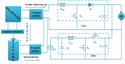
Figure 1 is realizing mainly with solar panel and proposed control strategy. The solar panel is used to charge the battery during sunlight available timings. The proposed control strategy comprises with MFB controller and fuzzy logic controller. Three control switches are connected between the battery, solar panel and unidirectional converter (UDC). The SOC of the battery and the output voltage of the solar panel decide the control switches (CS) ON and OFF conditions. The battery is connected to load through UDC on the other hand UC is connected to load through the bidirectional converter (BDC).
Figure 1. Proposed block diagram model of the hybrid energy storage system
Figure 2. Converter model circuit diagram with HESS
Converter model circuit with three switches present in UDC as well as BDC can be represented with Figure 2. The UDC contains only on switch S1 and switches S2, S3 are present in BDC. From three switches S1, S3 are used to boost the voltage level on the other hand S2 ON and OFF conditions decides the buck operation of the BDC to charge the UC during no-load condition on the electric vehicle.
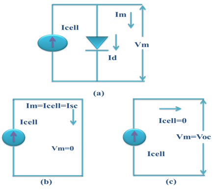
Single PV cell is capable of generates the voltage of less than one volt which means each Si photovoltaic cell develops the output voltage of around 0.7 V during open circuit time and 0.5 V under working condition. No. of cells are allied in series and parallel to assemble a PV module and a number of modules are allied in series and parallel to produce the required output. Using Si-based photovoltaic modules the PV system converts only 15% of solar energy into electricity. Perfect solar PV cell is demonstrated by a current source and an inverted diode coupled in parallel to it as shown in Figure 3.
Figure 3. (a) PV cell equivalent circuit, (b) PV cell at short circuit condition (c) PV cell at open circuit condition
Two key parameters are considered from the ideal circuit representation, as short-circuit current ($I_{S C}$) and open circuit voltage which are often used to illustrate the PV cell. By short-circuiting the terminals of the cell the photon generated current as shown in Figure 3(b), flows out of the cell called as a short circuit current ($I_{S C}$). Thus, we can say that $\mathrm{I}_{\text {cell }}=\mathrm{I}_{\mathrm{sc}}$ as the current $\mathbf{I}_{\text {cell }}$ is flowing in a single series circuit. As the terminals are short-circuited then the voltage across the circuit is equal to zero i.e $\mathrm{V}_{\mathrm{oc}}=0$ and the short-circuit current is the PV cell load current (or the output current which is very maximum as equal to that of the current source or photovoltaic photon generated current i.e. $\mathrm{I}_{\text {cell }}=\mathrm{I}_{\mathrm{sc}}=\mathrm{I}_{\mathrm{m}}$ Similarly, when the terminals are open circuited i.e. no load and nothing is connected as represented in 3 (c), the load current of a PV cell becomes zero. And the load voltage of a PV cell is equal to the maximum applied source voltage or open circuit voltage i.e. ($\mathrm{V}_{\mathrm{m}}=\mathrm{V}_{\mathrm{oc}}$).
The PV cell output current can found by applying KVL to circuit 3(a)
$\mathrm{I}_{\mathrm{m}}=\mathrm{I}_{\mathrm{cell}}-\mathrm{I}_{\mathrm{d}}$ (1)
The current through diode can be represented with bellow equation
$I_{d}=I_{\text {rscell}}\left[e^{\left(\frac{Q V}{K T a p}\right)-1}\right]$ (2)
By replacing Id in Equation 2, it gives the current-voltage association of the PV cell as shown below
$I_{m}=I_{c e l l}-I_{r s c e l l}\left[e^{\left(\frac{Q V}{K T a p}\right)-1}\right]$ (3)
The diode reverse saturation current $\mathrm{I}_{\mathrm{rscell}}$ ) is calculated by the open circuit condition of PV cell as illustrated in Figure 3(b). From the Equation (3) it is observed that $\mathrm{I}_{\mathrm{m}}=| 0$ and solve for $\mathrm{I}_{\mathrm{rscell}}$
$I_{\text {rscell}}=\frac{I_{\text {cell}}}{\left.\left[\frac{Q v}{(\text {KTap}}\right)-1\right]}$ (4)
The photon generated current is directly relative to the irradiance and temperature, on the other hand, voltage is directly relative to the irradiance and inversely proportional to the temperature. The value of ISCR is provided by the manufacturer datasheet at STC (standard test condition). At STC, the working temperature and irradiance are 250C and 1000 W/m respectively.
In the present work, the standard PV array has been taken and generated the power with different temperatures and irradiance values. Thereafter using DC-DC solar panel voltage has been changed according to the electric vehicle requirement. Here tree control switches have been connected to the solar panel, battery, and UDC. The SOC of the battery and the output voltage of the solar panel decide the control switches action. Finally, electrical vehicle requirement can be fulfilled using solar power based on the availability of sunlight.
4.1. Battery model
Figure 4. A dynamical model of a battery
Figure 4 shows that the dynamical model of the battery, where the terminal voltage is a function of time and is finding from three components.
$f_{1}\left(V_{t}, i_{1}, i\right)=E_{0}-\frac{K Q_{1}}{Q-V_{t}}-\frac{K Q V_{t}}{Q-V_{t}}+E \cdot \exp \left(-D \cdot V_{t}\right)$ (5)
$f_{1}\left(V_{t}, i_{1}, i\right)=E_{0}-\frac{K Q i_{1}}{V_{t}+0.1 Q}-\frac{K Q V_{t}}{Q-V_{t}}+E \cdot \exp \left(-D \cdot V_{t}\right)$ (6)
Where $\mathrm{E}_{0}$= constant voltage (V)
$\mathrm{SOC}=100\left(1-\frac{1}{\mathrm{Q}} \int_{0}^{\mathrm{t}} \mathrm{i}(\mathrm{t}) \mathrm{dt}\right)$ (7)
i=battery current
Q=Capacity of the battery (Ah)
$V_{t}$ =Extracted voltage (V)
E=Exponential voltage (V)
$i_{l}$=Low frequency current dynamics (A)
K=Polarization resistance (Ohms)
D=Exponential capacity (Ah-1)
4.2. Ultracapacitor model
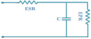
Figure 5. Equivalent electrical model of UC
Figure 5 representing that the equivalent electrical model of UC. The voltage state of UC for RC is given by stern-Tafel model of the UC is the most popular model and the equations of this model can be written as
$\mathrm{V}=\frac{\mathrm{NN}_{\mathrm{S}} \mathrm{Q} \mathrm{X} 2}{\mathrm{NN}_{\mathrm{p}} \mathrm{N}^{\wedge} 2 \varepsilon \varepsilon 0 \mathrm{A}}+\frac{\mathrm{NN}_{\mathrm{S}} 2 \mathrm{RT}}{\mathrm{F}} \alpha . r . \sinh \left(\frac{\mathrm{Q}}{\mathrm{N}_{\mathrm{p}} \mathrm{N}^{2 \mathrm{A} \sqrt{\mathrm{BR}} \mathrm{T} \varepsilon \varepsilon \mathrm{O} \mathrm{C}}}\right)$ (8)
$-\mathrm{i}(\mathrm{t})=\mathrm{Ai}_{0} \exp \left(\frac{\alpha \mathrm{F}\left(\frac{\mathrm{V}}{\mathrm{N}_{\mathrm{S}}}-\frac{\mathrm{V}_{\max }}{\mathrm{N}_{\mathrm{S}}}-\Delta \mathrm{V}\right)}{\mathrm{RT}}\right)$ (9)
$\mathrm{SOC}=\frac{\operatorname{Qinit}-\mathrm{f}_{0}^{\mathrm{t}} \mathrm{i}(\tau) \mathrm{d} \tau}{\mathrm{QT}} \times 100$ (10)
4.3. Unidirectional converter modeling
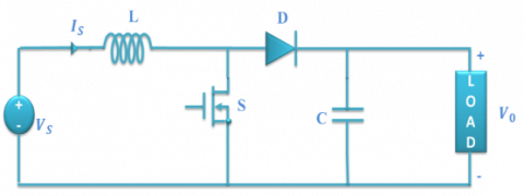
Figure 6. Unidirectional converter model
Figure 6 represents DC-DC Converter (boost), and the state space expression for the DC-DC converter (boost) during switch is in ON condition.
The generalized equation of UDC converter can be written as;
$\mathrm{V}=\mathrm{L} \frac{\mathrm{di}}{\mathrm{dt}}$ (11)
$\mathrm{i}=\frac{1}{\mathrm{L}} \int_{0}^{\mathrm{t}} \mathrm{V} \mathrm{d} \mathrm{t}+\mathrm{i}_{0}$ (12)
If the switch is in ON condition
$\mathrm{i}_{\mathrm{pk}}=\frac{\left(\mathrm{V}_{\mathrm{O}}-\mathrm{V}_{\mathrm{i}}\right) \mathrm{T}_{\mathrm{on}}}{\mathrm{L}}$ (13)
$\Delta \mathrm{i}=\frac{\left(\mathrm{V}_{\mathrm{O}}-\mathrm{VT}_{\mathrm{mos}}\right) \mathrm{T}_{\mathrm{on}}}{\mathrm{L}}$ (14)
If the switch is in OFF condition
$\mathbf{i}_{0}=\mathrm{i}_{\mathrm{pk}}=\frac{\left(\mathrm{V}_{\mathrm{O}}-\mathrm{V}_{\mathrm{i}}+\mathrm{V}_{\mathrm{D}}\right) \mathrm{T}_{\mathrm{off}}}{\mathrm{L}}$ (15)
or
$\Delta \mathrm{i}=\frac{\left(\mathrm{V}_{\mathrm{o}}-\mathrm{V}_{\mathrm{i}}+\mathrm{V}_{\mathrm{D}}\right) \mathrm{T}_{\mathrm{off}}}{\mathrm{L}}$ (16)
$V_{D}$=Diode across voltage drop, $V_{mos}$= Voltage drop across MOSFET
To find the $V_{o}$ value equate the $\Delta \mathbf{i}$ then,
$\mathrm{V}_{\mathrm{o}}=\frac{\mathrm{V}_{\mathrm{i}}-\mathrm{V}_{\mathrm{mos}} * \delta}{1-\delta}-\mathrm{V}_{\mathrm{D}}$ (17)
After neglecting the losses at MOSFET and Diode, the above equation becomes
$\mathrm{V}_{\mathrm{o}}=\frac{\mathrm{V}_{\mathrm{i}}}{1-\delta}$ (18)
Using the above equation (18) input voltage of the converter step up to a required voltage level by changing the duty cycle.
4.4. Bidirectional converter modeling
Change in inductor current can be represented with the below equation
$\frac{\mathrm{dI}_{\mathrm{L}}}{\mathrm{dt}}=\frac{\mathrm{V}_{\mathrm{i}}}{\mathrm{L}}$ (19)
Due to ON/OFF condition of the switch, current will change like,
$\Delta \mathrm{I}_{\mathrm{Lon}}=\int_{0}^{\delta \mathrm{T}} \mathrm{d} \mathrm{IL}=\int_{0}^{\delta \mathrm{T}} \frac{\mathrm{V}_{\mathrm{i}}}{\mathrm{L}} \mathrm{dt}=\frac{\mathrm{V}_{\mathrm{i}} \delta \mathrm{T}}{\mathrm{L}}$ (20)
The equation for IL can be written as;
$\frac{\mathrm{dIL}}{\mathrm{dt}}=\frac{\mathrm{V}_{0}}{\mathrm{L}}$ (21)
Therefore, the variation of
in the off-period is,$\Delta \mathrm{I}_{\text {Loff }}=\int_{0}^{(1-\delta) \mathrm{T}} \mathrm{d} \mathrm{IL}=\int_{0}^{(1-\delta) \mathrm{T}} \frac{\mathrm{V}_{0}}{\mathrm{L}} \mathrm{dt}=\frac{\mathrm{V}_{0}(1-\delta) \mathrm{T}}{\mathrm{L}}$ (22)
It is obvious that the sum of variations in IL for on-state and off-state should be zero. Hence
$\Delta \mathrm{I}_{\mathrm{Lon}}+\Delta \mathrm{I}_{\mathrm{Loff}}=0$ (23)
Substituting the equations of
$\Delta \mathrm{I}_{\mathrm{Lon}}+\Delta \mathrm{I}_{\mathrm{Loff}}=\frac{\mathrm{V}_{\mathrm{i}} \delta \mathrm{T}}{\mathrm{L}}+\frac{\mathrm{V}_{0}(1-\delta) \mathrm{T}}{\mathrm{L}}=0$ (24)
This can be written as,
$\frac{\mathrm{v}_{0}}{\mathrm{v}_{\mathrm{i}}}=\frac{\delta}{\delta-1}$ (25)
And
$\delta=\frac{\mathrm{V}_{\mathrm{o}}}{\mathrm{V}_{\mathrm{o}}-\mathrm{V}_{\mathrm{i}}}$ (26)
Figure 7. Bidirectional converter model
In this work mainly two controllers are used to achieve the proposed control scheme. The FLC is the first one and the second one is Math function based controller, the combination of this two controller forms a new controller to switch the energy sources of HESS according to the electric motor speed. Brief ideas about two controllers have given separately.
5.1. MFB controller
The MFB controller plays a key role during the generation of a pulse signal to the particular converter corresponding to the speed of an electric motor. The FLC produces the pulse signals to the converter by comparing the reference signal with actual signal, thereafter this error signal can be compared with the MFB generated signal and corresponding output signals has been applied to the converter switches. The converters applied signals are always corresponding to the speed of an electric motor, which can be controlled by the MFB controller. The designed MFB controller generates four math function signals according to the speed of an electric motor. In the first mode, math function U1 is in enable state, in second mode math functions U1, U2 are in enable state ate, during third mode U3 is in-active state and in final mode only U4 in-active state. All those states are use full to generates the pulse signals to the BD as well as UDC to switch the energy sources according to the speed of an electric motor. Here U1, U2, U3, and U4 are the generated output signals of the designed MFB controller.
5.2. Fuzzy logic controller
In this work mainly two controllers are used to achieve the proposed control scheme. The FLC is the one controller and the second one is Math function based controller, a combination of this two controller forms a new controller to switch the energy sources of hybrid energy storage system according to the electric motor speed. A brief idea about two controllers gave separately.
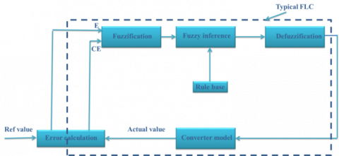
Figure 8. The typical structure of the Fuzzy logic controller
A typical structure of FLC has represented with Figure 3. Generally separate mathematical modeling is not required for generating a rectified signal from the fuzzy logic controller. Some membership functions are selected based on the requirement of the system; generally used shapes are triangular or trapezoidal. Thereafter inference has been done by using rule base; here rule base is used to manage the output variables. To obtain the final result from the fuzzy logic controller every rule base has been considered. Here error (E) and change in error (CE) both are considered as an input of the FLC system, which means the output of the FLC is a function of error and change in error.
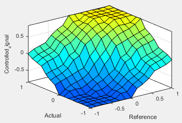
Figure 9. Surface viewer representation of the FLC
The overall circuit configuration is divided into four modes for a better understanding of the proposed control strategy and those four modes can found based on the applied load on the electric motor. Figure 10(a) represents the Mode-I operation, during this period a heavy load is applied to the electric motor and corresponding to that switch S3 is in an active state and other switches S2, S1 are in disable state. With that entire power requirement of the electric motor can be supplied by the UC. Figure 10(b) is related to slightly more than the rated load on the electric motor; during this period total power required by the motor can be met by the battery as well as UC. During this mode of operation the switches S1, S3 are in the active state whereas S2 is in disable state. Mode –III operation of the circuit can be represented with Figure 10(c), this is corresponding to a rated load on the motor, in this mode of operation total power required by the motor can supply by the battery only which means switch S1 only in ON position and remain two switches S2, S3 are in inactive state. Finally, Figure 10(d) can represent the no-load condition on the electric motor during these time switches S1, S2 are in ON condition and remain switch S3 is in disable state. During this mode of operation, the motor requires less amount of power that can be supplied by the battery along with that battery can supply some amount of power to UC.
Figure 10. Converter different modes circuit diagram with HESS (a) Mode-I, (b) Mode-II (c), Mode-III, (d) Mode-IV
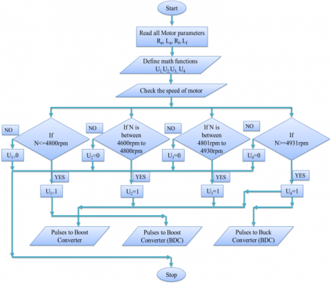
The proposed control technique is realized mainly with DC-DC converters and two controllers termed as an MFB controller as a well as FLC. The power requirement of the motor can be calculated corresponding to the speed of an electric motor which can be decided by the MFB controller and FLC is used to generating the pulse signals to switches connected in the DC-DC converters. The proposed control strategy can be explained by below flow chart.
(1) With a heavy load and starting of electric motor total power can be supplied by the UC only. The MFB controller generates out signal as 1 for math function U1 and also generates an output signal as 0 for remain math functions U2, U3, U4 corresponding to the speed of an electric motor. In this mode, the motor speed will be ≤ 4800 rpm and the BDC will be in operation which is connected at UC end. Finally, the designed MFB combined with other controller initiates to produce the controlled pulse signals to a particular converter.
(2) If slightly more than rated load is applied to an electric motor due to which motor speed is maintained between 4600 rpm to 4800 rpm. The MBF controller produces output signals as 1 for math functions U1, U2 and generates signals as 0 for remain math functions U3, U4 corresponding to the speed of an electric motor. Finally, controlled signals required by the converters can be generated by the designed MFB combined with another controller. UDC and BDC, both are in the active state, under boost mode. In this mode of operation, UC reduces the burden on the battery by sharing the transient power requirement of the load.
Figure 11. Flowchart of the proposed control strategy
(3) During this mode of operation rated load is applied to the electric motor, which leads to drawing average power by an electric motor. So batteries can delivery total power required by the load. Due to rated load, motor maintains a speed between 4801 rpm to 4930 rpm. The output pulse signal of the designed MFB generates as 1 for math function U3 and generates as 0 for remaining math functions U1, U2, U4 according to the speed of an electric motor. The designed MFB combined with other controller generates a controlled pulse signal to the UDC which will work under boost mode.
(4) During no load or light load condition, the battery is capable to deliver extra power to the load which is used to charge the UC. The output pulse signals of MBF controller generates as 1 for U4 and generates as 0 for U1, U2, and U3 according to the speed of an electric motor. The speed of motor maintained as >4931 rpm. The pulse signals are produced to BDC (buck mode) as well as UDC (boost mode).
Figure 12. Block diagram representation of converter switches for controlled pulse generation (a) for switch S1 (b) for switch S2 (c) for switch S3
Figure 12 (a), (b), (c) representing that how the control pulse signals are producing corresponding to the speed of an electric motor. Here the pulse signals are produced by the FLC and can be controlled by the MFB controller corresponding the speed of the electric motor which initiates the switching action between battery and UC. The pulse signals are producing the particular switch like based on bellow approach.
Pulse signal to switch S1: If MFB produces U2 or U3 or U4 then the pulse signal produced by the FLC can be applied to switch S1 to initiate the operation of UDC working under boost mode.
Pulse signal to switch S2: If MFB produces only U4 then the pulse signals produced by the FLC can be applied to switch S2 to initiate the operation of BDC working under buck mode.
Pulse signal to switch S3: If MFB produces U1 or U2 then the controlled pulses produced by the FLC can be applied to switch S3 to initiate the operation of BDC working under boost mode.
8.1. Mode-I operation results (Heavy load condition)
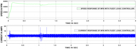
During the starting of motor subjected to, huge current and speed variation can be observed from above Figure 13. The speed response is settled within 0.6 sec during starting. Thereafter no variation found in both current and speed responses until the load is applied. At 1sec mode corresponding load is applied to the electric motor due to which current and speed variation presented, which are settled within 0.3 sec by the designed control strategy.
Figure 13. The responses corresponding to the speed and current of an electric motor
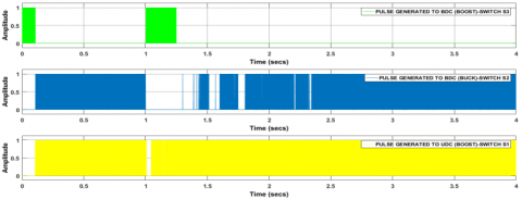
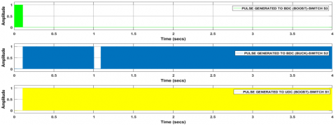
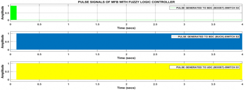
Figure 14. Controlled switching signals produced to BDC as well as UDC
During starting, the motor can start with UC, so the controlled signals are produced to BDC (boost mode) up to 0.1 sec. Thereafter controlled signals are produced to BDC (buck mode) as well as UDC (boost mode) till load applied to the electric motor. At 1 sec mode corresponding load is applied, due to which controlled signals are produced to BDC only (boost mode) until motor reached the steady state.
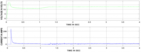
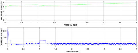
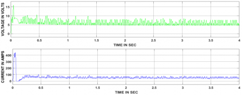
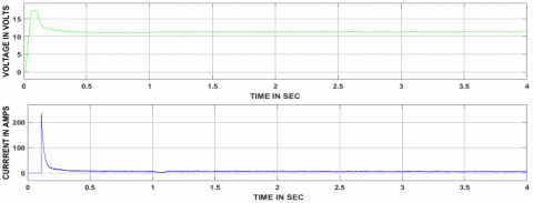
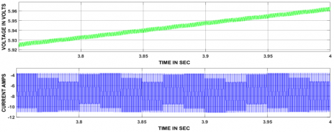
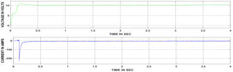
Figure 15. Responses of UDC corresponding to voltage and current at the input
Figure 16. Responses of UDC corresponding to voltage and current at the output
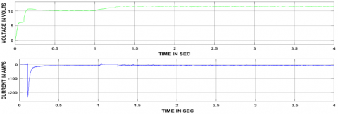
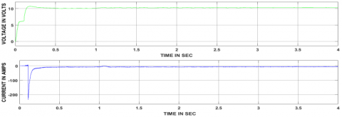
Figure 17. Responses of BDC corresponding to voltage and current at the input
Figure 18. Responses of BDC corresponding to voltage and current at the output
8.2. Mode-II operation results (Slightly more than rated load condition)
During starting motor subjected to, huge current and speed variation can be observed from above Figure 19. The speed response is settled within 0.6 sec during starting. Thereafter no variation found in both current and speed responses until the load is applied. At 1 sec mode corresponding load is applied to the electric motor due to which current and speed variation presented, which are settled with 0.2 sec by the designed control strategy.
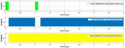
At 1 sec mode corresponding load is applied, due to which controlled signals are produced to BDC (boost) and UDC (boost) until motor reached the steady state. Thereafter again controlled signals are generated to BDC (buck) as well as UDC (boost).
Figure 19. The responses corresponding to the speed and current of an electric motor
Figure 20. Controlled switching signals produced to BDC as well as UDC
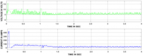
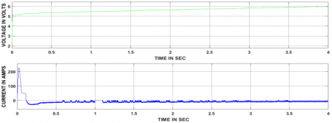
Figure 21. Responses of UDC corresponding to voltage and current at the input
Figure 22. Responses of UDC corresponding to voltage and current at the output
Figure 23. Responses of BDC corresponding to voltage and current at the input
Figure 24. Responses of BDC corresponding to voltage and current at the output
8.3. Mode-III results (Rated load condition)
During starting of motor subjected to, huge current and speed variation can be observed from above figure 25. The speed response is settled within 0.6 sec during starting. Thereafter no variation found in both current and speed responses until the load is applied. At 1 sec mode corresponding load is applied to the electric motor due to which small current and speed variation presented, which are settled with 0.09 sec by the designed control strategy.
At 1 sec mode corresponding load is applied, due to which controlled signals are produced to only UDC (boost) and no signals to BDC until motor reached the steady state. Thereafter again controlled signals are generated to BDC (buck) as well as UDC (boost).
Figure 25. The responses corresponding to the speed and current of an electric motor
Figure 26. Controlled switching signals produced to BDC as well as UDC
Figure 27. Responses of UDC corresponding to voltage and current at the input
Figure 28. Responses of UDC corresponding to voltage and current at the output
Figure 29. Responses of BDC corresponding to voltage and current at the input
Figure 30. Responses of BDC corresponding to voltage and current at the output
8.4. Mode-IV results (No load condition)
During starting of motor subjected to, huge current and speed variation can be observed from above figure 31. The speed response is settled within 0.6 sec during starting. Thereafter no variation found in both current and speed responses until the load is applied. In this mode, no load is applied.
Figure 31. The responses corresponding to the speed and current of an electric motor
Figure 32. Controlled switching signals produced to BDC as well as UDC
During starting, the motor can start with UC, so the controlled signals are produced to BDC (boost mode) up to 0.1 sec. Thereafter controlled signals are produced to BDC (buck mode) as well as UDC (boost mode) till load applied to the electric motor. In this mode no load is applied, so no further changes will appear.
Figure 33. Responses of UDC corresponding to voltage and current at the input
Figure 34. Responses of UDC corresponding to voltage and current at the output
Figure 35. Responses of BDC corresponding to voltage and current at the input
Figure 36. Responses of BDC corresponding to voltage and current at the output
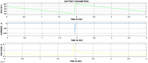
8.5. Battery parameters
In present work battery minimum SOC has taken 20%, if battery SOC is bellowed 20% then it should get charged from the solar power directly after that again discharges the same amount of power to the electric vehicle until its SOC reaches to 20%. From the above Figure 37, it is clear that during discharging time the battery current showing positive whereas shown negative value under the charging period.
Figure 37. The battery parameters during charging and discharging periods
8.6. PV array parameters
Figure 38 represents the solar panel input parameters and duty cycle value connected at the UDC side. Here solar power can be generated based on the irradiance and temperature availability. And with different values of irradiance, temperature power has been produced at various voltage levels. Different variations of temperature and irradiance can be observed from the above Figure 38.
Figure 38. Solar panel parameters and duty cycle of the converter
Table 1. Comparison of four modes of operation after applying a load
|
Controller |
Time is taken to reach steady state after applying load on the electric motor |
|||
|
Mode-I |
Mode-II |
Mode-III |
Mode-IV |
|
|
MFB with Fuzzy |
0.3 sec |
0.2 sec |
0.009 sec |
No load applied |
Table 2. DC-DC converters ON/OFF states based on the mode of operation
|
S. No |
Type of mode |
State of UDC |
State of BDC |
Power flow direction |
|
1 |
Mode-I |
Off |
Boost |
UC supply power to load |
|
2 |
Mode-II |
Boost |
Boost |
Battery and UC together supply power to Load |
|
3 |
Mode-III |
Boost |
Off |
Battery only supply power to load |
|
4 |
Mode-IV |
Boost |
Buck |
The batter can supply power to load as well as UC |
Table 1 indicates that the time taken to reach steady state during each mode of operation depending upon the load applied to the motor. In a mode –I a heavy load is applied at 1sec due to which motor speed reduced to less than 4600 rpm thereafter the motor has taken 0.3sec to obtain the stable state. Similarly, in mode-II, slightly more than the rated load is applied, due to which motor speed reduces to between 4600 rpm to 4800 rpm thereafter motor has taken 0.2 sec to obtain a stable state. Finally, in mode-III rated load is applied due to that motor speed maintains near to 4930 rpm thereafter the motor has taken 0.009 sec to obtain a stable state. During mode-IV, no load is applied to the motor.
Table 3. MFB controller outputs corresponding to speed
|
S. No |
Speed condition associated with mode |
ON State Math Function |
|
1 |
If Speed is ≤4800 rpm |
U1=1 & U2=0, U3=0, U4=0 |
|
2 |
If Speed is from 4600 rpm to 4800 rpm |
U1=1, U2=1 & U3=0, U4=0, |
|
3 |
If Speed is from 4801 rpm to 4930 rpm |
U3=1 & U1=0, U2=0, U4=0 |
|
4 |
If Speed is >4931 rpm |
U4=1 & U1=0, U2=0, U3=0 |
The MFB controller is designed and integrated with the fuzzy logic controller, made a new control strategy to switch the energy source in HESS corresponding to the speed of an electric motor. The proposed control strategy is implemented to the electric motor mainly in four modes based on the applied load. During the first mode of operation a heavy load is applied, and the controlled signals are produced to BDC working under boost mode and no controlled signals are produced to UDC, in mode two operation slightly more than rated load is applied to the motor and corresponding to that pulse signals are generated to BDC as well as UDC both are working under boost mode. In mode three, the rated load is applied to the electric motor, corresponding to that pulses are produced to UDC working under boost mode and no pulse signals are produced to BDC. Finally, in mode four, no load is applied due to which the controlled signals are produced to BDC working under buck mode and UDC working under boost mode. In all modes of operation proposed control strategy has given satisfactory results during switching of battery and UC according to the electric vehicle dynamics.
Ghiassi-Farrokhfal Y., Kazhamiaka F., Rosenberg C., Keshav S. (2015). Optimal design of solar PV farms with storage. IEEE Transactions on Sustainable Energy, Vol. 6, No. 4, pp. 1586-1593. http://dx.doi.org/10.1109/TSTE.2015.2456752
Hu S., Liang Z., He X. (2016). Ultracapacitor-battery hybrid energy storage system based on the asymmetric bidirectional Z-source topology for EV. IEEE Transactions on Power Electronics, Vol. 31, No. 11, pp. 7489-7498. http://dx.doi.org/10.1109/TPEL.2015.2493528
Jung H., Wang H., Hu T. (2014). Control design for robust tracking and smooth transition in power systems with battery/supercapacitor hybrid energy storage devices. Journal of Power Sources, Vol. 267, pp. 566-575. http://dx.doi.org/10.1016/j.jpowsour.2014.05.061
Keil P., Englberger M., Jossen A. (2016). Hybrid energy storage systems for electric vehicles: An experimental analysis of performance improvements at subzero temperatures. IEEE Transactions on Vehicular Technology, Vol. 65, No. 3, pp. 998-1006. http://dx.doi.org/10.1109/TVT.2015.2486040
Li J., Zhang M., Yang Q., Zhang Z., Yuan W. (2016). SMES/battery hybrid energy storage system for electric buses. IEEE Transactions on Applied Superconductivity, Vol. 26, No. 4, pp. 1-5. http://dx.doi.org/10.1109/TASC.2016.2527730
Liu N., Chen Q., Lu X., Liu J., Zhang J. (2015). A charging strategy for PV-Based battery switch stations considering service availability and self-consumption of PV energy. IEEE Trans. Industrial Electronics, Vol. 62, No. 8, pp. 4878-4889. http://dx.doi.org/10.1109/TIE.2015.2404316
Moreno J., Ortúzar M. E., Dixon J. W. (2006). Energy-management system for a hybrid electric vehicle, using ultracapacitors and neural networks. IEEE transactions on Industrial Electronics, Vol. 53, No. 2, pp. 614-623. http://dx.doi.org/10.1109/TIE.2006.870880
Ren G., Ma G., Cong N. (2015). Review of electrical energy storage system for vehicular applications. Renewable and Sustainable Energy Reviews, Vol. 41, pp. 225-236. http://dx.doi.org/10.1016/j.rser.2014.08.003
Sadagopan S., Banerji S., Vedula P., Shabin M., Bharatiraja C. (2014, April). A solar power system for electric vehicles with maximum power point tracking for novel energy sharing. In India Educators' Conference (TIIEC), 2014 Texas Instruments, pp. 124-130. http://dx.doi.org/10.1109/TIIEC.2014.029
Shen J., Khaligh A. (2015). A supervisory energy management control strategy in a battery/ultracapacitor hybrid energy storage system. IEEE Transactions on Transportation Electrification, Vol. 1, No. 3, pp. 223-231. http://dx.doi.org/10.1109/TTE.2015.2464690
Shen J., Khaligh A. (2016). Design and real-time controller implementation for a battery-ultracapacitor hybrid energy storage system. IEEE Transactions on Industrial Informatics, Vol. 12, No. 5, pp. 1910-1918. http://dx.doi.org/10.1109/TII.2016.2575798
Song Z., Li J., Han X., Xu L., Lu L., Ouyang M., Hofmann H. (2014). Multi-objective optimization of a semi-active battery/supercapacitor energy storage system for electric vehicles. Applied Energy, Vol. 135, pp. 212-224. http://dx.doi.org/10.1016/j.apenergy.2014.06.087
Trovao J. P. F., Santos V. D., Antunes C. H., Pereirinha P. G., Jorge H. M. (2015). A real-time energy management architecture for multisource electric vehicles. IEEE Trans. Industrial Electronics, Vol. 62, No. 5, pp. 3223-3233. http://dx.doi.org/10.1109/TIE.2014.2376883