OPEN ACCESS
Nowadays Microgrids have placed a major role because usage of electrical energy is increased. In this work Microgrid having three DGs photo voltaic energy, wind energy, and fuel cell. Here in a microgrid, the frequency and powers are matched on the source side and load side by using PLL measurement circuits. Due to the combining of three DGs fault current levels are increased, that fault current is limited using R-SFCL (Resistive type superconducting fault current limiter) R-SCL gives a very fast response and limits fault current magnitudes in the first half cycle. R-SFCL is not improving complete transient stability because the presence of reactive components in the transmission line so voltage profile is not balanced, at that situation by using Series active power filters we balance the voltage profile, increases the power transfer capability, reduce the harmonics and improvement of transient stability in Microgrids. Series active power filters are introducing the reactive components into the transmission line then transmission line reactive power is balanced. This planned effort is done using MATLAB / Simulink.
distributed generation (DG), resistive type superconducting fault current limiter (R-SFCL), phase locked loop (PLL), series active power filter (SAPF)
In this work Microgrid having three DGs photo voltaic energy, wind energy, and fuel cell. Here in a microgrid, the frequency and powers are matched on the source side and load side by using PLL measurement circuits. Due to the combining of three DGs fault current levels are increased, that fault current is limited using R-SFCL (Resistive type superconducting fault current limiter) R-SFCL gives a very fast response and limits fault current magnitudes in the first half cycle. R-SFCL is not improving complete transient stability because the presence of reactive components in the transmission line so voltage profile is not balanced, at that situation by using Series active power filters we balance the voltage profile, increases the power transfer capability, reduce the harmonics and improvement of transient stability in Microgrids R-SFCL gives a very fast response and limit fault current magnitudes in the first half cycle generally it creates low impedance path at microgrid is in healthy condition and it creates high impedance path at faulty conditions due to that high impedance fault currents are limited Generally, conservative protective devices like circuit breaker and relays have not protected the system in a good manner, because conservative protective devices having some time delay so it allows one to two cycles of short-circuit currents due to that short-circuit currents the system is damaged. R-SFCL limit fault current within the first half cycle then the system is protected from abnormal conditions. R-SFCL having the following advantages less weight, occupies less space and high efficiency. To maintain complete transient stability I added series active power filters (SAPF) into the transmission lines generally series active power filters inject the reactive components into the transmission lines; these reactive components reduce the reactive power in the transmission line. The main aim of the series active power filter is to balance the voltage profile, increases the power transfer capability, reduce the harmonics and improvement of transient stability in microgrids is not improving complete transient stability because presence of reactive components in the transmission line so voltage profile is not balanced and power transfer capability is reduced, at that situation by using SAPF we balance the voltage profile, increases the power transfer capability, reduce the harmonics and improvement of transient stability in Microgrids. SAPF having a power source, load, converter, hysteresis controller, injection transformer and filter. SAPF connected in between the source and load SAPF is mainly used for filtering current harmonics, reduce voltage distortions (sag, swell). In SAPF hysteresis controller is always compare operating voltage with a reference voltage and it generates gate pulses that gate pulse gives to inverter then inverter send that compensated voltages to a transmission line with the help of injection transformer the structure of the series active power filter. Here hybrid system consists three DGs Fuel cell, P-V power, and Wind power these three DGs are interconnected with main grid, here fuel cell can supply 10 KW, P-V power can supply 250KW and Wind power supply 150KW to loads. we connected three 3-phase inductive loads these capacities are (150+j25) KVA, (450+j30) KVA and (200+j20) KVA respectively. Here rating of the transmission line is (0.27+j0.347) Ω/km frequency of the microgrid is designed to50 Hz, voltage levels at transmission level is10.5 KV and at distribution level 415 volts. This distribution level 415 volts gives to the loads. Microgrids have placed a major role because usage of electrical energy is increased. In this work Microgrid having three DGs photo voltaic energy, wind energy, and fuel cell. Here in a microgrid, the frequency and powers are matched on the source side and load side by using PLL measurement circuits. Due to the combining of three DGs fault current levels are increased, that fault current is limited using R-SFCL (Resistive type superconducting fault current limiter) R-SCL gives a very fast response and limits fault current magnitudes in the first half cycle. R-SFCL is not improving complete transient stability because the presence of reactive components in the transmission line so voltage profile is not balanced, at that situation by using Series active power filters we balance the voltage profile, increases the power transfer capability, reduce the harmonics and improvement of transient stability in Microgrids. Series active power filters are introducing the reactive components into the transmission line then transmission line reactive power is balanced. Generally, conservative protective devices like circuit breaker and relays have not protected the system in a good manner, because conservative protective devices having some time delay so it allows one to two cycles of short-circuit currents due to that short-circuit currents the system is damaged. R-SFCL limit fault current within the first half cycle then the system is protected from abnormal conditions. R-SFCL having the following advantages less weight, occupies less space and high efficiency. It has one shunt element (Inductive/Resistive), this element is protected Resistive type superconducting fault current limiter from abnormal conditions. In microgrid we create one LLL-G fault in wind distributed generation; the fault time is 0.08 sec to 0.12 sec at that instant short circuit current is raises up to 1250 amperes. When R-SFCL is connected in the power system network then fault current is reduces to 800 amps, because R-SFCL acts as a high impedance path at the time of fault. When SAPF is connected to the power system network then fault current is reduces to 700 amps, because voltage levels are compensated. R-SCL gives a very fast response and limits fault current magnitudes in the first half cycle. R-SFCL is not improving complete transient stability because the presence of reactive components in the transmission line so voltage profile is not balanced, at that situation by using Series active power filters (SAPF) we balance the voltage profile, increases the power transfer capability, reduce the harmonics.
Integrated Microgrid protection is very difficult because the combination of two or more DGs, these DGs interconnection with the main grid is also difficult to process and identification of fault is difficult. In the process of distributed generators interconnection short-circuit currents are increased this short circuit current is known as fault currents, due to that short-circuit currents voltage levels are reduced and power transfer capability is reduced finally system not having stability in high voltage applications. At that situation our conservative protective devices like circuit breaker and relays have not protected the system in a good manner, generally conservative protective devices having some time delay so it allows one to two cycles of short circuit currents. To overcome these disadvantages Resistive type superconducting fault current limiter and Series active power filters are introduced.
R-SFCL gives a very fast response and limit fault current magnitudes in the first half cycle generally R-SFCL creates low impedance path at microgrid is in healthy condition and it creates high impedance path at faulty conditions due to that high impedance fault currents are limited. Moon Fil-jong said R-SFCL is a good device to reduce short circuit currents within the first half cycle (Moon & Kim, 2013). X Ying. said the operation, advantages, and applications of R-SFCL (Liu et al., 2015).
To maintain complete transient stability I added series active power filters (SAPF) into the transmission lines generally series active power filters inject the reactive components into the transmission lines; these reactive components reduce the reactive power in the transmission line. The main aim of the series active power filter is to balance the voltage profile, increases the power transfer capability, reduce the harmonics and improvement of transient stability in Microgrids. Here fault is created at wind distributed generator using MATLAB/Simulink. The obtained results are meet our requirement the system is working effectively (Sung et al., 2009; Tsai, 2004).
Inside R-SFCL gives a very fast response and limit fault current magnitudes in the first half cycle generally it creates low impedance path at microgrid is in healthy condition and it creates high impedance path at faulty conditions due to that high impedance fault currents are limited.
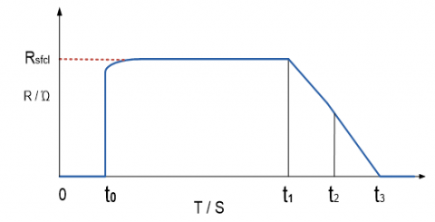
Referred from (Moon et al., 2013). And (Lo et al., 2011). Mathematical modelling of R-SFCL is
$R(t)=\left\{\begin{array}{cc}{0} & {t<t_{0}} \\ {R_{S F C L}\left[1-\exp \left(-\frac{t-t_{0}}{\tau}\right)\right]^{1 / 2}} & {t_{0} \leq t<t_{1}} \\ {a_{1}\left(t-t_{1}\right)+b_{1}} & {t_{1} \leq t<t_{2}} \\ {a_{2}\left(t-t_{2}\right)+b_{2}} & {t_{2} \leq t}\end{array}\right.$
RSFCL = normal resistance of SFCL
τ = time constant
t0, t1 and t2 are the different time intervals
a1, a2, b1 and b2 are the different coefficients
Figure. 1 indicates the recovery and quench characteristics of R-SFCL at different time intervals, at each interval R-SFCL resistance is changed.
Figure 1. Recovery and quench characteristics of R-SFCL
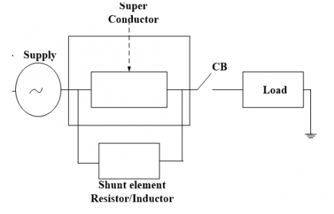
Generally, conservative protective devices like circuit breaker and relays have not protected the system in a good manner, because conservative protective devices having some time delay so it allows one to two cycles of short-circuit currents due to that short-circuit currents the system is damaged. R-SFCL limit fault current within the first half cycle (Chenetal, 2014). then the system is protected from abnormal conditions. R-SFCL having the following advantages less weight, occupies less space and high efficiency. It has one shunt element (Inductive/Resistive), this element is protected Resistive type superconducting fault current limiter from abnormal conditions as shown in figure 2.
Figure 2. Super conducting fault current limiter (Resistive type)
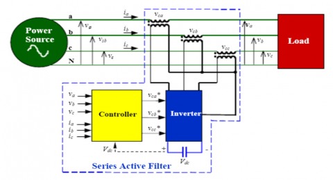
R-SFCL is not improving complete transient stability because presence of reactive components in the transmission line so voltage profile is not balanced and power transfer capability is reduced, at that situation by using SAPF we balance the voltage profile, increases the power transfer capability, reduce the harmonics and improvement of transient stability (Kim et al., 2004). in Microgrids. SAPF having a power source, load, converter, hysteresis controller, injection transformer and filter. SAPF connected in between the source and load SAPF is mainly used for filtering current harmonics, reduce voltage distortions (sag, swell). In SAPF hysteresis controller is always compare operating voltage with a reference voltage and it generates gate pulses (Ribeiro & Barbi, 2006), that gate pulse gives to inverter then inverter send that compensated voltages to a transmission line with the help of injection transformer the structure of the series active power filter is shown in figure 3. In SAPF hysteresis controller operation depends upon the following equation.
$V_{I N J}=V_{L}-V_{S}$
VINJ = Injected voltage
VL = Voltage at load
VS = Voltage at source
Figure 3. Series active power filter
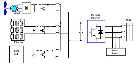
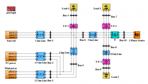
This hybrid system consists three DGs Fuel cell, P-V power, and Wind power these three DGs are interconnected with main grid, here fuel cell can supply 10 KW, P-V power can supply 250KW and Wind power supply 150KW to loads.
In this power system network, we connected three 3-phase inductive loads these capacities are (150+j25) KVA, (450+j30) KVA and (200+j20) KVA respectively. Here rating of the transmission line is (0.27+j0.347) Ω/km frequency of the microgrid is designed to50 Hz, voltage levels at transmission level is10.5 KV and at distribution level 415 volts. This distribution level 415 volts gives to the loads as shown in the figure. 4.
Figure 4. Hybrid power system
This microgrid is developed using MATLAB/Simulink, as compared to PSPICE and EMTP Matlab having so many advantages. Figure.5 shows the Simulink diagram of microgrid without fault.
Figure 5. Simulink diagram of microgrid without fault
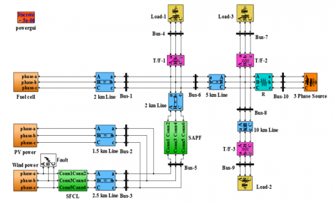
Figure.6 shows the Simulink diagram of a microgrid with LLL-G fault, R-SFCL and series active power filter (SAPF).
Figure 6. Simulink diagram of a microgrid with LLL-G fault, R-SFCL and SAPF
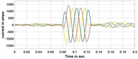
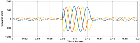
In microgrid we create one LLL-G fault in wind distributed generation; the fault time is 0.08 sec to 0.12 sec at that instant short circuit current is raises up to 1250 amperes as shown in the figure 7.
Figure 7. Short circuit currents near the fault
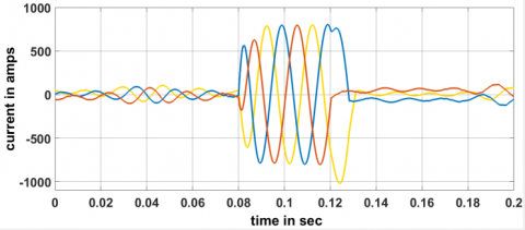
When R-SFCL is connected in the power system network then fault current is reduces to 800 amps, because R-SFCL acts as a high impedance path at the time of fault as shown in the figure 8.
Figure 8. Short circuit currents near the fault using R-SFCL
When SAPF is connected to the power system network then fault current is reduces to 700 amps, because voltage levels are compensated as shown in the figure 9.
Figure 9. Short circuit currents near the fault using R-SFCL and SAPF
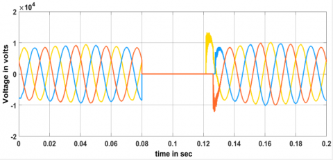
In microgrid we create one LLL-G fault in wind distributed generation; the fault time is 0.08 sec to 0.12 sec at that instant voltage levels are reduced from 10.5 KV as shown in the figure 10.
Figure 10. The voltage at fault location
Whenever R-SFCL is connected in the power system network, the fault current is reduced then voltages are nearly compensated. Due to the presence of reactive components voltage levels are not completely compensated as shown in the figure 11.
Figure 11. The voltage at fault location using R-SFCL
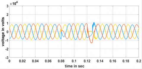
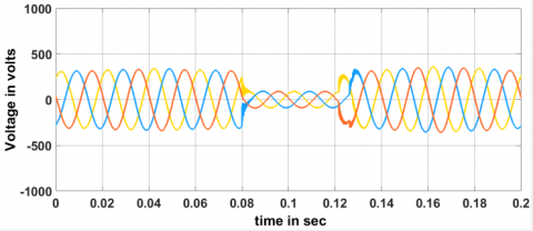
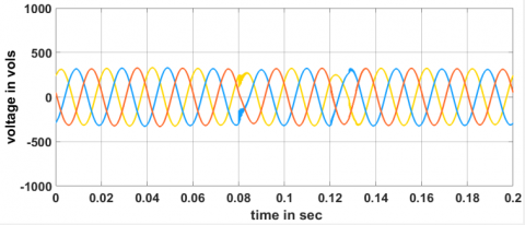
In microgrid we create one LLL-G fault at wind distributed generation; the fault time is 0.08 sec to 0.12 sec at that instant maximum voltage per phase is reduced at load 1, load 2 and load 3 as shown in the figure 12.
Figure 12. voltages at load-1, load-2 and load-3
Figure 13. voltages at load-1, load-2 and load-3 using R-SFCL
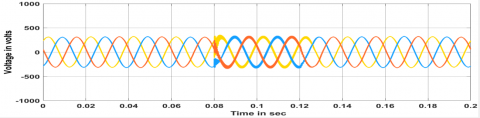
When R-SFCL is connected in the power system network, the fault current is reduced then load voltages are nearly compensated. Due to the presence of reactive components load voltages are not completely compensated as shown in the figure 13.
Whenever SAPF is connected in the power system network then fault current is reduces as well as load voltages are completely compensated because of the injection of reactive components in the transmission line as shown in the figure 14.
Figure 14. voltages at load-1, load-2 and load-3 using R-SFCL and SAPF
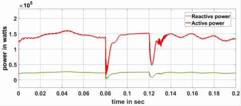
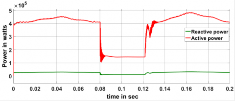
In microgrid we create one LLL-G fault at wind distributed generation; the fault time is 0.08 sec to 0.12 sec at that instant voltage levels are reduced and fault currents are increases then power levels are reduced from (150+j25) KVA as shown in the figure 15.
Figure 15. Under fault power on load-1
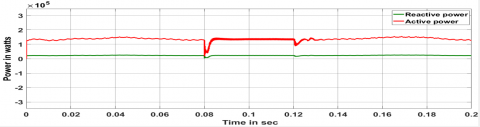
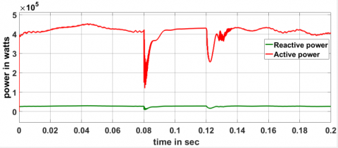
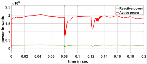
When R-SFCL is connected in the power system network, the fault current is reduced and load voltages are nearly compensated. Then power levels are nearly compensated Due to the presence of reactive components load power levels are not completely compensated as shown in the figure 16.
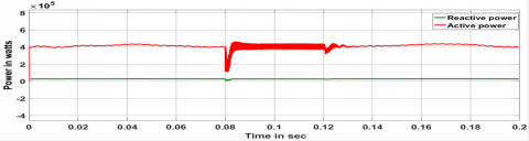
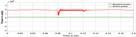
When SAPF is connected in the power system network then fault current is reduces as well as load voltages are completely compensated because injection of reactive components in the transmission line, finally power transfer capability increases as shown in the figure 17.
Figure 16. Under fault power on load-1 using R-SFCL
Figure 17. Under fault power on load-1 using R-SFCL and SAPF
In microgrid we create one LLL-G fault at wind distributed generation; the fault time is 0.08 sec to 0.12 sec at that instant voltage levels are reduced and fault currents are increases then powers are reduced from (450+j30) KVA as shown in the figure 18.
Figure 18. Under fault power on load-2
Whenever R-SFCL is connected in the power system network, the fault current is reduced and load voltages are nearly compensated. Then power levels are nearly compensated Due to the presence of reactive components load power levels are not completely compensated as shown in the figure 19.
Figure 19. Under fault power on load-2 using R-SFCL
Whenever SAPF is connected in the power system network then fault current is reduces as well as load voltages are completely compensated because injection of reactive components in the transmission line, finally power transfer capability increases as shown in the figure 20.
Figure 20. Under fault power on load-2 using R-SFCL and SAPF
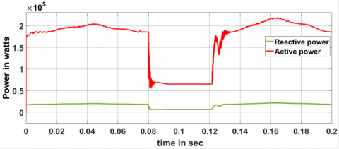
In microgrid we create one LLL-G fault at wind distributed generation; the fault time is 0.08 sec to 0.12 sec at that instant voltage levels are reduced and fault currents are increases then power levels are reduced from (200+j20) KVA as shown in the figure 21
Figure 21. Under fault power on load-3
R-SFCL is connected in the power system network, the fault current is reduced and load voltages are nearly compensated. Then power levels are nearly compensated Due to the presence of reactive components load power levels are not completely compensated as shown in the figure 22.
Figure 22. Under fault power on load-3 using R-SFCL
SAPF is connected in the power system network then fault current is reduces as well as load voltages are completely compensated because injection of reactive components in the transmission line, finally power transfer capability increases as shown in the figure 23.
Figure 23. Under fault power on load-3 using R-SFCL and SAPF
In this work Microgrid having three DGs photovoltaic energy, wind energy, and fuel cell. Due to the combining of three DGs fault current levels are increased, that fault current is limited using R-SFCL (Resistive type superconducting fault current limiter) R-SCL gives a very fast response and limits fault current magnitudes in the first half cycle. R-SFCL is not improving complete transient stability because the presence of reactive components in the transmission line so voltage profile is not balanced, at that situation by using Series active power filters (SAPF) we balance the voltage profile, increases the power transfer capability, reduce the harmonics and improvement of transient stability in Microgrids.
Chenetal L. (2014). Reducing the fault current and overvoltage in a distribution system with distributed generation units through an active type SFCL. IEEETrans. Appl. Supercond., Vol. 24, No. 3, Art.no. 5600305. https://doi.org/10.1109/TASC.2013.2281493
Kim Y. S., Kim J. S., Ko S. H. (2004). Three-phase three-wire series active power filter, which compensates for harmonics and reactive power. IEE Proceedings - Electric Power Applications, Vol. 151, No. 3, pp. 276-282. https://doi.org/10.1049/ip-epa:20040208
Liu W. D., Jiang X. H., Zhang R. J., Qian J. L. (2015). The Recent research and development of superconducting fault current limiter. Electrotechnical Journal, Vol. 9, No. 3, pp. 1-9. https://doi.org/10.3969/j.issn.1672-9560.2001.08.004
Lo B., Lau S., Cheung S., Allen N. (2011). Assessment of the impact of SFCL on voltage sags in power distribution system. IEEE Transactions on Applied Superconductivity, Vol. 26, No. 2, pp. 209-223. https://doi.org/10.1080/02699931.2011.574997
Moon J. F., Kim J. S. (2013). Voltage sag analysis in loop power distribution system with SFCL. IEEE Transactions on Applied Superconductivity, Vol. 23, No. 3, No. 5601504. https://doi.org/10.1109/TASC.2013.2238374
Moon S. W., Won N. J., Huh S. J., Kim C. J. (2013). A study on the application of a superconducting fault current limiter for energy storage protection in a power distribution system. IEEE Transactions on Applied Superconductivity, Vol. 23, No. 3, pp. 5603404-5603404. https://doi.org/10.1109/TASC.2013.2238594
Ribeiro R. E., Barbi I. (2006). Harmonic voltage reduction using a series active filter under different load conditions. IEEE Transactions on Power Electronics, Vol. 21, No. 5, pp. 1394-1402. https://doi.org/10.1109/TPEL.2006.880265
Sung B., Park D., Park J., Ko T. (2009). Study on optimal location of a resistive SFCL applied to an electric power grid. IEEE Trans. Appl. Supercond., Vol. 19, No. 3, pp. 2048–2052. https://doi.org/10.1109/TASC.2009.2019035