Adil Yahdou* | Abdelkadir Belhadj Djilali | Zinelaabidine Boudjema | Fayçal Mehedi
© 2020 IIETA. This article is published by IIETA and is licensed under the CC BY 4.0 license (http://creativecommons.org/licenses/by/4.0/).
OPEN ACCESS
This work presents a new control strategy for counter-rotating wind turbine (CRWT) driven doubly-fed induction generator (DFIG) under grid disturbances, such as unbalanced network voltage scenarios. The proposed strategy based on the power control used dynamic gains second order sliding mode control (SOSMC). The power control of a DFIG by SOSMC widely based on the super-twisting (ST) algorithm with invariable parameters and sign functions. The proposed control method consists in using dynamic-parameters ST algorithm that ensures a better result than a conventional strategy. The proposed control scheme used 2 sliding surfaces such as reactive and active powers to control them. Also, the sign functions are replaced by saturation (sat) functions in order to minimize the chattering problems. Simulation results depicted in this research article have confirmed the good usefulness and effectiveness of the proposed adaptive super-twisting algorithm of the CRWT system during grid disturbances.
adaptive gains, counter-rotating wind turbine, doubly fed induction generator, grid disturbances, saturation functions, second order sliding mode
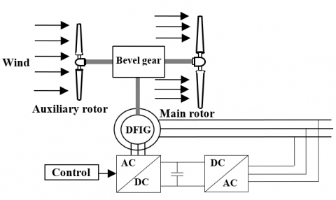
The CRWT has been presented as a novel wind turbine (WT) to increase the production of the electrical energy, as depicted in Figure 1, CRWT design contain of 2 rotors (main rotor and auxiliary rotor). According to the literature [1, 2], the principal advantage of CRWT is the improvement of system yield.
The DFIG is generally the most popular applied WT generators due the fact that it is cost-effective and its variable wind speed [3, 4]. However, wind turbine system based DFIGs are sensitive to disturbance grid voltage conditions due to the direct connection between the grid and DFIG. As a result, if the machine regulator does not take into consideration the effects of unbalanced network voltage conditions, stator and rotor currents will be perturbed. Also, electromagnetic torque, reactive and active powers will be subjected to a lot of perturbations. The generator should tolerate all these types of network voltage situations and scenarios. It should appear an acceptable performance basing to power network codes [5, 6].
The standard control method of network-attached DFIG are widely based on a vector control (VC) method with stator flux orientation [7, 8] or stator voltage orientation [9, 10]. In these methods of control, proportional gain-integral gain (PI) regulators are used to regulate DFIG powers through adjusting components of rotor currents. The principal disadvantage of VC methods is that adjusting PI gains is cumbersome. Also, these PI regulators are sensitive to parameter variations of DFIG and unbalanced network voltage scenarios.
Some researchers have been applied sliding mode control (SMC) method for power electronics field [11, 12]. But there exist different methods to SMC, the following three being the most commonly adopted: standard first-order SMC [13, 14], non-standard first-order SMC and second-order SMC [15]. However, the principal drawback jeopardizing usefulness of the standard first-order SMC: namely, the chattering phenomenon mainly caused by the discontinuous control.
Nevertheless, the non-standard first-order SMC resolve this problem by replacing the sign function with a boundary layer approach such as the sigmoid or the saturation functions. However, as shown in the study [16], this approach does not overcome the disadvantage completely, because, the characteristics of tracking accuracy, disturbance rejection and robustness conferred by the non-standard first-order SMC are severely compromised.
With the goal to resolve these problems, the SOSMC method with the ST algorithm control laws was published in the study [17]. The discontinuous function under the integral characterizes the fixed parameters ST algorithm method. In fixed gains ST algorithm control law, the over-estimation of the disturbance boundary gives bigger control gain values which lead to chattering phenomenon [18]. To resolve this problem, in this paper, we applied the ASOSMC.
The principal goal of this research article is the application of the ASOSMC to control the stator powers of generator driven by CRWT system during grid disturbances. The new second original contribution of this article is to replace the sign functions of adaptive-gain ST algorithm by saturation functions (sat) in order to minimize the chattering problems.
This work presents the principal aspects of the power adaptive second-order sliding mode control (ASOSMC) and simulation results using Matlab/Simulink for a CRWT system. The ASOSMC method is compared with a conventional power SOSMC with a fixed gain ST algorithm.
This research article contains five parts as follows: in part two, the DFIG modeling is presented. In part three the VC method of the DFIG is depicted. The ASOSMC applied to the DFIG is developed in part 4. Finally, part five presents the obtained simulation results and its discussion.
Figure 1. Configuration of a counter-rotating wind turbine
The DFIG Park model is generally used [19-26]. The following Eq. (1) shows the global generator Park model:
$\left\{\begin{array}{l}V_{d s}=R_{s} I_{d s}+\frac{d}{d t} \phi_{d s}-\omega_{s} \varphi_{q s} \\ V_{q s}=R_{s} I_{q s}+\frac{d}{d t} \phi_{q s}+\omega_{s} \varphi_{d s} \\ V_{d r}=R_{r} I_{d r}+\frac{d}{d t} \phi_{d r}-\omega_{r} \varphi_{q r} \\ V_{q r}=R_{r} I_{q r}+\frac{d}{d t} \phi_{q r}+\omega_{r} \varphi_{d r}\end{array},\left\{\begin{array}{l}\phi_{d s}=L_{s} I_{d s}+M I_{d r} \\ \phi_{q s}=L_{s} I_{q s}+M I_{q r} \\ \phi_{d r}=L_{r} I_{d r}+M I_{d s} \\ \phi_{q r}=L_{r} I_{q r}+M I_{q s} \\ \omega_{s}=\omega_{m}+\omega_{r}\end{array}\right.\right.$ (1)
The mechanical equation is:
$C_{e m}=C_{r}+J \frac{d \Omega}{d t}+f \Omega$ (2)
where,
$C_{e m}=p \frac{M}{L_{s}}\left(\phi_{q s} I_{d r}-\phi_{d s} I_{q r}\right)$ (3)
Here, Cem is the electromagnetic torque.
The stator powers (Psand Qs) delivered from the generator is given by:
$\left\{\begin{array}{l}P_{s}=V_{d s} I_{d s}+V_{q s} I_{q s} \\ Q_{s}=V_{q s} I_{d s}-V_{d s} I_{q s}\end{array}\right.$ (4)
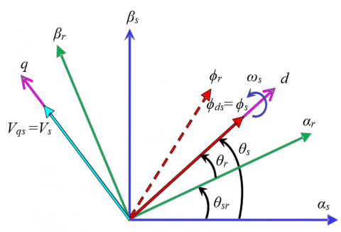
In the objective to achieve the decoupled control (vector control) of the stator powers of generator, the stator flux vector will be oriented on the d-axis (Figure 2). Based on Eq. (1), the stator resistance is neglected (Rs= 0) we can write:
$\phi_{d s}=\phi_{s} \quad$ and $\quad \phi_{q s}=0$ (5)
$\left\{\begin{array}{l}V_{d s}=0 \\ V_{q s}=V_{s}=\omega_{s} \phi_{s}\end{array}\right.$ (6)
$\left\{\begin{array}{l}I_{d s}=-\frac{M}{L_{s}} I_{d r}+\frac{V_{s}}{L_{s} \omega_{s}} \\ I_{q s}=-\frac{M}{L_{s}} I_{q r}\end{array}\right.$ (7)
By using Eqns. (5), (6) and (7), Eq. (4) becomes:
$\left\{\begin{array}{l}P_{s}=-V_{s} \frac{M}{L_{s}} I_{q r} \\ Q_{s}=\frac{V_{s}^{2}}{\omega_{s} L_{s}}-\frac{V_{s} M}{L_{s}} I_{d r}\end{array}\right.$ (8)
The electromagnetic torque of Eq. (3) becomes:
$C_{e m}=-p \frac{M}{L_{s}} I_{q r} \phi_{d s}$ (9)
Figure 2. Stator field oriented control
In the objective to control the stator powers of the generator under unbalanced network voltage, ASOSMC is applied with an adaptive ST algorithm. This control strategy is continuous, and its parameters are adapted to eliminate the effect of the perturbation with the unknown boundaries, also, non overestimate the gains. As well as, the objective of the corrector is that its adaptation allows reducing the gain with respect to disturbances and uncertainties. Then, the parameter is reduced and the regulator spends less energy. Also, another big advantage is the considerable reduced effort of system identification. As a result, the information on disturbances bounds and uncertainties is not required.
The used ASOSMC laws are given by:
$u=u_{1}+u_{2}$ (10)
$\dot{u}_{1}=-\beta \cdot \operatorname{sat}(s)$ (11)
$u_{2}=-\alpha \cdot|s|^{\frac{1}{2}} \cdot \operatorname{sat}(s)$ (12)
where, the adaptive gains of ASOSMC, α and β are dynamics, given us:
$\left\{\begin{array}{ll}\dot{\alpha}=\left\{\begin{array}{lll}\omega \sqrt{\frac{\psi}{2}} \operatorname{sat}(|s|-\mu) & , \text {if } & \alpha>\alpha_{m} \\ \eta & , \text {if } & \alpha \leq \alpha_{m}\end{array}\right. \\ \beta=2 \varepsilon \alpha\end{array}\right.$ (13)
where ε, μ, αm, η, ω, ѱ: are positive constant.
The dynamical parameters of ASOSMC increases in order to achieve the stabilization. Then, if the sliding mode is maintained, the control parameters begin to decrease.
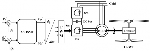
The proposed ASOSMC is developed to control the stator powers of the DFIG; it is illustrated in Figure 3.
According to Eqns. (10), (11), (12) and (13). The ASOSMC laws are given by:
$V_{d r}^{*}=-\alpha_{3} \cdot\left|s_{3}\right|^{\frac{1}{2}} \cdot \operatorname{sat}\left(s_{3}\right)-\int_{0}^{t} \beta_{3} \cdot \operatorname{sat}\left(s_{3}\right) d \tau$ (14)
$V_{q r}^{*}=-\alpha_{4} \cdot\left|s_{4}\right|^{\frac{1}{2}} \cdot \operatorname{sat}\left(s_{4}\right)-\int_{0}^{t} \beta_{4} \cdot \operatorname{sat}\left(s_{4}\right) d \tau$ (15)
Here, the active power magnitude error $s_{4}=P_{s}^{*}-P_{s}$ and the reactive error $s_{3}=Q_{s}^{*}-Q_{s}$ are the sliding surfaces. The adaptive gains αi and βi (i=3, 4) are expressed as the Eq. (13).
$\left\{\begin{array}{lll}\dot{\alpha}_{i}=\left\{\begin{array}{ll}\omega_{i} \sqrt{\frac{\psi_{i}}{2}} \operatorname{sat}\left(\left|s_{i}\right|-\mu_{i}\right) & , \text {if } & \alpha_{i}>\alpha_{m i} \\ \eta_{i} & , \text {if } & \alpha_{i} \leq \alpha_{m i}\end{array}\right. \\ \beta_{i}=2 \varepsilon_{i} \alpha_{i}, i=3,4\end{array}\right.$ (16)
Figure 3. ASOSMC of a CRWT based on DFIG
The proposed control (ASOSMC) depicted in part 4 was validated, using the MATLAB/Simulink software.
The DFIG parameters are [21]: 1.5 MW nominal power, Vs=398 V, Rr=0.021 Ω, Rs=0.012 Ω, Lr=0.0136 H, Ls=0.0137 H, M=0.0135 H, fs=50 Hz, nominal rotor speed Ω=150 rad/s, p=2.
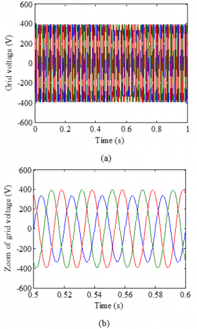
Unbalanced network voltage is considered in all simulation cases, According to Figure 4, a 15% grid voltage drop in phase A between 0.5 and 0.7 s is considered. The performances of the both power control methods SOSMC and ASOSMC are simulated and compared.
5.1 Reference tracking test (RTT)
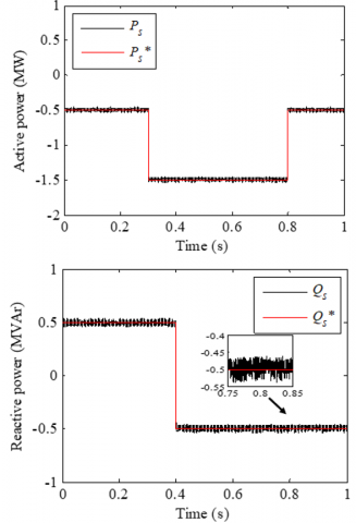
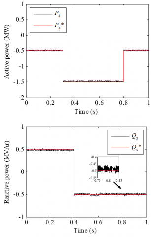
In this first test the DFIG rotor speed is equal at its nominal value (Ω=150 rad/s). Figures 5-7 present obtained simulation results for the RTT. As illustrated in Figures 5 and 6, for the 2 powers control methods (SOSMC and ASOSMC), the reactive and active powers of DFIG almost perfectly track their references.
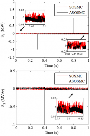
The time evolution of the sliding surfaces s3 and s4 obtained using the fixed-gain ST algorithm (SOSMC) and adaptive-gain ST algorithm (ASOSMC) are depicted in Figure 7. The SOSMC and the time-based ASOSMC achieved the desired goals, steering to and confining the sliding surfaces (s3 and s4) within a vicinity of zero in the two cases. Nevertheless, a significant chattering phenomenon reduction can be observed when the proposed control is employed.
5.2 Robustness test (RT)
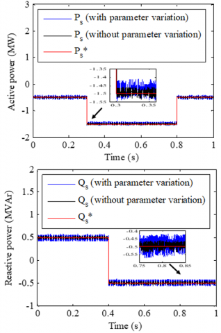
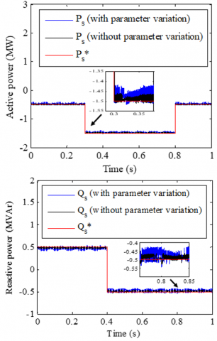
In this second test, it is supposed that the rotor resistance (Rr) value is increased up to 100%. Also, the values of inductances Ls, Lr, M are decreased up to 50%. The DFIG is turning with constant speed (Ω=150 rad/s). Obtained results for the RT are depicted in Figures 8-10. As shown by Figures 8 and 9, we noticed that on the reactive and active power curves, the generator parameter variations present a clear effect. This effect is more important for power SOSMC method than for power ASOSMC. Therefore, it can be concluded that the proposed power ASOSMC technique is more robust than the power SOSMC one.
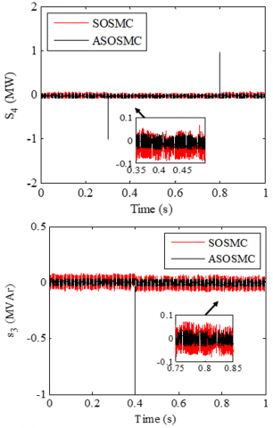
Figure 10 presents the time evolution of the sliding surfaces s3 and s4 for the robustness test. As shown in this Figure, the chattering phenomenon appears more important when the power SOSMC is applied. In the other hand, this chattering is minimized for the power ASOSMC one.
Figure 4. Simulation results. (a) grid voltage, (b) zoom of grid voltage
Figure 5. Stator powers with SOSMC (RTT)
Figure 6. Stator powers with the proposed ASOSMC (RTT)
Figure 7. Sliding surfaces (RTT)
Figure 8. Stator powers with SOSMC (RT)
Figure 9. Stator powers with the proposed ASOSMC (RT)
Figure 10. Sliding surfaces (RT)
5.3 Rotor speed variation test (RSVT)
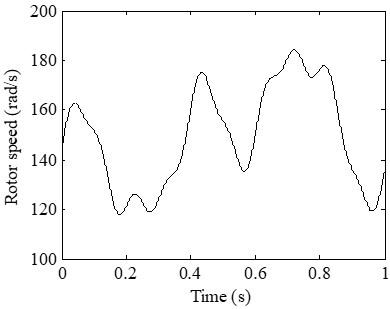
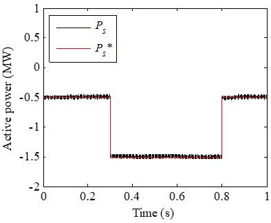
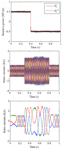
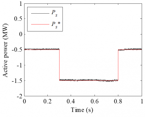
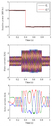
As depicted by Figure 11, the rotor speed of the DFIG was randomly varied. The results obtained are depicted in Figures 12-15. These Figures illustrate that the variation of the DFIG rotor speed gives a ripple effect on reactive and active power curves of DFIG for power SOSMC. This active and reactive powers ripple is minimized for the power ASOSMC. Also, a rotor currents ripple can be observed during the period of unbalanced network voltage for the power SOSMC. This rotor currents ripple is minimized for the power ASOSMC. This simulation result is important for CRWT system applications guarantee the quality and stability of the produced energy when the rotor speed of DFIG is randomly varying.
Figure 11. Rotor speed curve
Figure 12. Active power with SOSMC (RSVT)
Figure 13. Reactive power, stator currents, rotor currents with SOSMC (RSVT)
Figure 14. Active power with ASOSMC (RSVT)
Figure 15. Reactive power, stator currents and rotor currents with ASOSMC (RSVT)
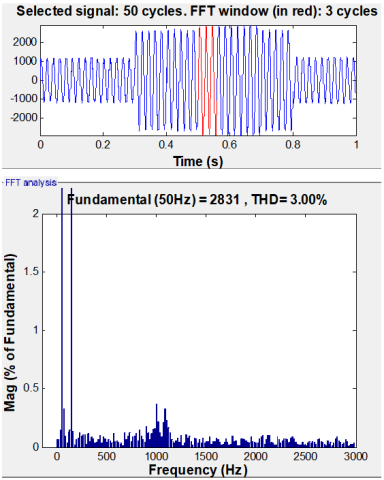
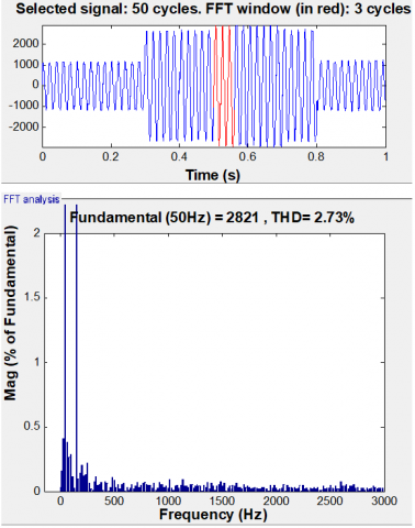
Figures 16-17 illustrate the THD of the stator current of the DFIG for both stator power control methods (SOSMC and ASOSMC) during the unbalanced network voltage for rotor speed variation test. It can be noticed that the THD value is reduced for stator power ASOSMC strategy (THD=2.73%) compared to SOSMC (THD=3.00%).
Figure 16. Stator current THD for SOSMC (RSVT)
Figure 17. Stator current THD for ASOSMC (RSVT)
ASOSMC of a CRWT based DFIG connected to the grid by the stator under grid disturbances has been presented in this research work. Obtained results show a good quality performance of ASOSMC compared to SOSMC with fixed-gains ST algorithm in terms of reduced chattering problems, and shows an excellent robustness test for variation parametric. Also, for the rotor speed variation test, the simulation results for the proposed control (ASOSMC) illustrate a reduction of THD value, stator power and rotor current ripple during unbalanced network voltage. Finally, it can be concluded that a control technique such as ASOSMC can be a very effective solution for stator power control of DFIG driven by CRWT system.
|
ASOSMC |
Adaptive Second Order Sliding Mode Control |
|
DFIG |
Doubly-Fed Induction Generator |
|
CRWT |
Counter Rotating Wind Turbine |
|
PI |
Proportional-Integral |
|
RSC |
Rotor Side Converter |
|
RSVT |
Rotor Speed Variation Test |
|
RTT |
Reference Tracking Test |
|
RT |
Robustness Test |
|
sat |
Saturation function |
|
SMC |
Sliding Mode Control |
|
SOSMC |
Second Order Sliding Mode Control |
|
ST |
Super-Twisting |
|
SSC |
Stator Side Converter |
|
THD |
Total Harmonic Distortion |
|
VC |
Vector Control |
|
WT |
Wind Turbine |
|
d, q |
Synchronous d-q axis |
|
Rr , Rs |
Rotor and stator resistances |
|
Lr, Ls |
Rotor and stator self-inductances |
|
M |
Mutual inductance |
|
Vds, Vqs |
Direct and quadrature stator voltages |
|
Vdr, Vqr |
Direct and quadrature rotor voltages |
|
Ids, Iqs |
Direct and quadrature stator currents |
|
Idr, Iqr |
Direct and quadrature rotor currents |
|
ϕds, ϕqs |
Direct and quadrature stator flux |
|
ϕdr, ϕqr |
Direct and quadrature rotor flux |
|
Ps, Qs |
Active and reactive powers |
|
Cem |
Electromagnetic Torque |
|
Ω |
Mechanical rotor speed |
|
Cr |
Load Torque |
|
f |
Viscous friction coefficient |
|
J |
The inertia |
|
p |
Number of pole pairs |
|
ωs |
Stator electrical pulsation |
|
ωr |
Rotor electrical pulsation |
|
ωm |
Mechanical pulsation |
|
α, β |
Adaptive gains |
|
s3, s4 |
Sliding surfaces |
[1] Cho, W., Lee, K., Choy, I., Back, J. (2017). Development and experimental verification of counter-rotating dual rotor/dual generator wind turbine. Generating, yawing and furling. Renewable Energy, 114: 644-654. https://doi.org/10.1016/j.renene.2017.06.083
[2] Lee, S., Son, E., Lee, S. (2013). Velocity interference in the rear rotor of a counter-rotating wind turbine. Renewable Energy, 54: 235-240. https://doi.org/10.1016/j.renene.2012.08.003
[3] Wang, X., Sun, D., Zhu, Z.Q. (2017). Resonant-based backstepping direct power control strategy for DFIG under both balanced and unbalanced grid conditions. IEEE Transactions on Industry Applications, 53(5): 4821-4830. https://doi.org/10.1109/TIA.2017.2700280
[4] Prajapat, G.P., Senroy, N., Kar, I.N. (2017). Wind turbine structural modeling consideration for dynamic studies of DFIG based system. IEEE Transactions on Sustainable Energy, 8(4): 1463-1472. https://doi.org/10.1109/TSTE.2017.2690682
[5] Nian, H., Cheng, P., Zhu, Z.Q. (2015). Independent operation of DFIG-based WECS using resonant feedback compensators under unbalanced grid voltage conditions. IEEE Transactions on Power Electronics, 30(7): 3650-3661. https://doi.org/10.1109/TPEL.2014.2346190
[6] Muyeen, S.M., Takahashi, R., Murata, T., Tamura, J. (2010). A variable speed wind turbine control strategy to meet wind farm grid code requirements. IEEE Transactions on Power Systems, 25(1): 331-340. https://doi.org/10.1109/TPWRS.2009.2030421
[7] Pena, R., Clare, J.C., Asher, G.M. (1996). Doubly fed induction generator using back-to-back PWM converters and its application to variable-speed wind energy generation. IEE Proceedings-Electric Power Applications, 143(3): 231-241. https://doi.org/10.1049/ip-epa:19960288
[8] Xu, L., Cheng, W. (1995). Torque and reactive power control of a doubly fed induction machine by position sensorless scheme. IEEE Transactions on Industry Applications, 31(3): 636-642. https://doi.org/10.1109/28.382126
[9] Muller, S., Deicke, M., De Doncker, R.W. (2002). Doubly fed induction generator systems for wind turbines. IEEE Industry Applications Magazine, 8(3): 26-33. https://doi.org/10.1109/2943.999610
[10] Hu, J., He, Y. (2006). Dynamic modelling and robust current control of wind-turbine driven DFIG during external AC voltage dip. Journal of Zhejiang University-Science A, 7: 1757-1764. https://doi.org/10.1631/jzus.2006.A1757
[11] Shang, L., Hu, J. (2012). Sliding-mode-based direct power control of grid-connected wind-turbine-driven doubly fed induction generators under unbalanced grid voltage conditions. IEEE Transactions on Energy Conversion, 27(2): 362-373. https://doi.org/10.1109/TEC.2011.2180389
[12] Chen, S.Z., Cheung, N.C., Wong, K.C., Wu, J. (2010). Integral sliding-mode direct torque control of doubly-fed induction generators under unbalanced grid voltage. IEEE Transactions on Energy Conversion, 25(2): 356-368. https://doi.org/10.1109/TEC.2009.2036249
[13] Utkin, V.I. (1993). Sliding mode control design principles and applications to electric drives. IEEE Transactions on Industrial Electronics, 40(1): 23-36. https://doi.org/10.1109/41.184818
[14] Martinez, M.I., Tapia, G., Susperregui, A., Camblong, H. (2012). Sliding-mode control for DFIG rotor-and grid-side converters under unbalanced and harmonically distorted grid voltage. IEEE Transactions on Energy Conversion, 27(2): 328-339. https://doi.org/10.1109/TEC.2011.2181996
[15] Susperregui, A., Martinez, M.I., Zubia, I., Tapia, G. (2012). Design and tuning of fixed-switching-frequency second-order sliding-mode controller for doubly fed induction generator power control. IET Electric Power Applications, 6(9): 696-706. https://doi.org/10.1049/iet-epa.2011.0358
[16] Young, K.D., Utkin, V.I., Ozguner, U. (1999). A control engineer’s guide to sliding mode control. IEEE Transactions on Control Systems Technology, 7(3): 328-342. https://doi.org/10.1109/87.761053
[17] Levant, A., (1993). Sliding order and sliding accuracy in sliding mode control. International Journal of Control, 58(6): 1247-1263. https://doi.org/10.1080/00207179308923053
[18] Shtessel, Y., Taleb, M., Plestan, F. (2012). A novel adaptive-gain supertwisting sliding mode controller: Methodology and application. Automatica, 48(5): 759-769. https://doi.org/10.1016/j.automatica.2012.02.024
[19] Kahla, S., Soufi, Y., Sedraoui, M., Bechouat, M. (2015). On-off control based particle swarm optimization for maximum power point tracking of wind turbine equipped by DFIG connected to the grid with energy storage. International Journal of Hydrogen Energy, 40(39): 13749-13758. https://doi.org/10.1016/j.ijhydene.2015.05.007
[20] Yaichi, I., Semmah, A., Wira, P. (2019). Direct power control of a wind turbine based on doubly fed induction generator. European Journal of Electrical Engineering, 21(5): 457-464. https://doi.org/10.18280/ejee.210508
[21] Boudjema, Z., Taleb, R., Djeriri, Y., Yahdou, A. (2017). A novel direct torque control using second order continuous sliding mode of a doubly fed induction generator for a wind energy conversion system. Turkish Journal of Electrical Engineering & Computer Sciences, 25(2): 965-975. https://doi.org/10.3906/elk-1510-89
[22] Benbouhenni, H., Boudjema, Z., Belaidi, A. (2020). DPC based on ANFIS super-twisting sliding mode algorithm of a doubly-fed induction generator for wind energy system. Journal Européen des Systèmes Automatisés, 53(1): 69-80. https://doi.org/10.18280/jesa.530109
[23] Abdeddaim, S., Betka, A. (2013). Optimal tracking and robust power control of the DFIG wind turbine. International Journal of Electrical Power & Energy Systems, 49: 234-242. https://doi.org/10.1016/j.ijepes.2012.12.014
[24] Yahdou, A., Boudjema, Z., Taleb, R., Belhadj Djilali, A. (2018). Backstepping sliding mode control of a dual rotor wind turbine system. 2018 International Conference on Electrical Sciences and Technologies in Maghreb (CISTEM), Algiers, pp. 1-5. https://doi.org/10.1109/CISTEM.2018.8613409
[25] Yahdou, A., Hemici, B., Boudjema, Z. (2015). Sliding mode control of dual rotor wind turbine system. The Mediterranean Journal of Measurement and Control, 11(2): 412-419.
[26] Boudjema, Z., Taleb, R., Yahdou, A. (2016). A new DTC scheme using second order sliding mode and fuzzy logic of a DFIG for wind turbine system. International Journal of Advanced Computer Science and Applications, 7(8): 49-56. https://doi.org/10.14569/IJACSA.2016.070808