Arckarakit Chaithanakulwat
© 2020 IIETA. This article is published by IIETA and is licensed under the CC BY 4.0 license (http://creativecommons.org/licenses/by/4.0/).
OPEN ACCESS
This research paper presents an optimization of shunt active power filter with proportional integral (PI) control in three-phase three-wire power systems. The method of optimization is to create a prototype shunt active power filter three-phase connected to the grid system with three-phase, three-wire, non-linear load supply to provide harmonics current monitors that occur in the system are reduced. This research has the advantage of using a three-phase waveform voltage detection principle to generate one reference sine signal and calculate the current for compensation when compared to the harmonic current generated in the system. The compensated current will be used for PWM modulation with a hysteresis principle to control the three-phase shunt active power filter. That can control the follow-up current harmonic that occurs in the system. The results of the prototype equipment testing show that when the non-linear load is not shared by the parallel power filter prototype equipment with PI control, there is a total harmonic distortion of current in the grid system 40.56%. Conversely, when combined with the prototype of the power filter, the shunt active power filter with PI control causes the total harmonic distortion of current is reduced to 13.79%. Consequently, increasing the optimization of shunt active power filter with PI control in the three-phase three-wire power system can confirm that the method this will be used to develop and apply in the industry that there is a harmonic current generating device in the system.
hysteresis current band, shunt active filter power, non-linear load, total harmonic distortion, inverter
There are currently many types of loads used with three-phase systems, most of these loads are electronic devices that are non-linear loads. These loads are all caused the waveform voltage and current in the system to distort from the sine waveform. These loads cause the quality of power in the system to decrease. Nevertheless, from the foregoing, this is the part that produces the sum of the harmonic currents in increasing grid systems, resulting in distortion in sensitive electrical and electronic equipment. Consequently, to solve the problem of harmonic current distortion, commonly used is the use of passive power filter circuit filter for filtering out harmonic. Notwithstanding, but it is still not able to completely solve the harmonic problem, so a shunt active power filter circuit has been developed to support the solution. The design of the shunt active power filter circuit to work optimally, there are factors to consider is to create a workpiece that can work with the type of load.
Nevertheless, control methods and current generation methods that are to be referenced to be accurate for this research, therefore, have developed a prototype device to improve the power quality of a three-phase power system with a shunt active power filter to be used to solve distortion. Causing harmonic this shunt active power filter controls the modulation by the hysteresis current technique before using the simulation results of the MATLAB/Simulink program to develop and design a prototype for harmonic current control in grid systems. Consequently, the development shunt active power filter uses hysteresis current control techniques to generate pulse width modulation signals into the shunt active power filter circuit to compensate for distorted currents that have waveforms approaching sine waveform. These principles will result in longer distortion in electrical and electronic components that are more sensitive to these distortions.
An experimental study of DC bus voltage control of three-phase shunt active power filter (APF). The controller is used to improve the tracing characteristics of power quality and reduce the use of reactive power. To specify the reference current used for the algorithm according to the self-adjustment filter (STF). The generation of pulses of inverters using isolate gate bipolar transistor (IGBT) devices with a hysteresis current controller, which is brought to use with analog cards. When testing parallel active filters with IGBTs, non-linear loads and a dSPACE digital prototyping system for creating references of harmonic currents and analog cards to control harmonic currents. The test results under both fixed and transient conditions show consistent signal flow graphs and analysis and are in accordance with meeting the IEEE 519-1992 recommended harmonic standard limits [1, 2]. Predictive direct power control for shunt active power filters. The main goal is to eliminate unwanted harmonics and compensate for basic reactive power from non-linear loads. Dynamically controlled, highly dynamic, it can improve performance by performing a real-time operation on dSPACE 1104 cards in a fixed and temporary state. Comparative results between simulation and testing have similar values, which prove and verify the effectiveness of the proposed control strategy [3]. The squirrel cage induction generator connected to the wind turbine will encounter problems of power quality and malfunction of the grid system. The state-of-art technique is used to meet the requirements of low-voltage (LVRT) to compensate for the reactive power. Nevertheless, reverse resistance and energy storage systems also affect work efficiency. Independent, both positive and negative control methods of the static compensator (STATCOM) hybrid and the serial resistance resistor (SDBR) will improve LVRT performance to reduce voltage fluctuations. The simulation results of MATLAB show that the new method can reduce the voltage fluctuation and increase the efficiency of LVRT [4, 5]. The photovoltaic system connects a single-phase grid that uses the active power filtering function that can transfer excess power to the grid to compensate for reactive power and harmonic for non-linear loads. Resulting in grid currents almost identical to the sine waveform and having a power factor nearly unity power. Moreover, the above system will use the dSPIC30F4011 microcontroller to control the operation. The operating process creates a prototype machine to compare with the simulation in various operating modes. The simulation results and comparison with the prototype machine found that the various modes can work correctly and can compensate for reactive power and harmonics can achieve objectives [6-10]. The optimized control of the shunt active power filter (SAPF) in a balanced three-phase balanced three-wire system, including improved control strategies, will be implemented in synchronous reference frames (SRF). Compared to repetitive the general control (RC) versus the conventional RC (CRC). Nevertheless, the proposed strategy can shorten the time period, resulting in a faster dynamic response and can also detect the harmonic in SRF based on the sliding Discrete Fourier transform [11]. Modelling algorithm and the implementation of three-phase DSTATCOM using self-tuning filters according to the instantaneous reactive power theory, control of power quality improvement. To be used for harmonic removal, load balancing and reactive power compensation at the voltage connection point under non-linear loads. The adaptive fuzzy logic control algorithm is used to control bus voltage to improve response, reduce overload and undershoot of traditional PI control. The simulation results of the algorithm in MATLAB/Simulink programs and real-time operation of DSTATCOM through digital signal processor dSPACE 1104 has satisfactory performance [12]. The function of active power filters under grid connection conditions will have significant fluctuations in grid frequencies and harmonics. Adaptive digital control for the three-phase APF in the grid and variable frequency connection conditions, consisting of an adjustable resonant current regulator, adjustable grid resonator and synchronous reference-phase locking loop, reference-frame. For phase locked loop (PLL), it uses stable filter adjustment steps to improve the grid phase and estimate the frequency of the harmonic voltage. This PLL frequency estimation will improve the resonance of the current PI to include vector-proportional-integral-integrative current control model, making APF can maintain the efficiency of the phase grid [13]. The SAPF power filter is automatically activated when needed to compensate with the specified capacitors. However, the strategy traditional flow limits cannot be covered by specified objectives. A good current limiting pattern based on particle swarm optimization to achieve this goal is the reduction of total harmonic distortion (THD) for grid currents, the maximum utilization ratio of SAPF capacity. The main advantage is limiting the optimal flow of each harmonic command in real-time to achieve flexible control and ultimately, simulation and testing confirm the effectiveness of the proposed strategy [14]. Reducing harmonic currents are important in delivering power to non-linear loads. The construction of an active power filter (APF) device which is able to control the current harmonic distortion dynamically and eliminate asymmetric loads. The compensation efficiency of the APF will depend on the control strategy used by the voltage source inverter (VSI). Model predictive control has been proven to be an effective control method. For VSIS control, which is different from traditional control methods, the proposed technique is the shunt discrete-time model. APF to predict the behaviour of harmonic currents and set the power supply function to increase efficiency [15].
Nevertheless, from the literature mentioned above, all are for principles of different strategies and methods in order to improve the electricity quality in the grid system altogether. Consequently, for this paper, simple principles are used to control the harmonics occurring in the system when the load-supply and the grid-connected to the specified standards. Such a principle is to control pulse width modulation (PWM) with the follower-based principle of PI control, which allows the system to provide more power and also keeps the power factor of the system within the standard better. The topics discussed below, consisting of the proposed format and related principles, fundamentals of power related to shunt active power filters, hysteresis band current control, PID control system, design of PI controllers and power factor control, Accordingly, results and discussion and finally concluded.
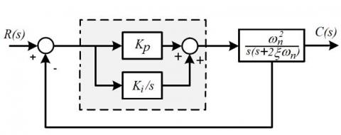
Consider Figure 1, in a three-phase, three-wire power system that is the connection in the delta system supplied to the non-linear load. Non-linear loads are most often caused by electronic circuits containing a large number of semiconductors and may have a type of load induction motor for a single-phase or three-phase, etc. Nevertheless, these loads will result in reduced power quality due to a large amount of harmonics in the system. Consequently, this research therefore designed to increase efficiency with a three-phase shunt active power filter connected to the grid system with a three-phase, three-wire, non-linear load supplied to enable the harmonic current generated in the reduced system.
From Figure 1, the principle and method are that when the non-linear load supplied system detects the waveform current supplied to the load through the filter current control mechanism to be calculated in comparison with the reference current obtained from the three-phase voltage is a reference sine waveform through the reference current regeneration mechanism. Moreover, the voltage across the capacitor is taken through the reference current regeneration mechanism and is used to calculate the current used for compensation when compared to the harmonic current generated in the system. The compensated current will be used for PWM modulation with a hysteresis principle to control the three-phase shunt active power filter that can control the follow-up harmonic current that occurs in the system. Nevertheless, for the design of the optimization device, the researchers will present the function with PI control and without PI control to compare the efficiency and performance of both functions with the MATLAB/Simulink program through dsPTMS320f28335 microcontroller. Which will show details in the next topic.
Figure 1. Schematic the principle and method of three-phase shunt active power filter system
2.1 The shunt active power filter
Analysis of a three-phase circuit is generally analyzed as a three-phase circuit. The calculation of the sum of active, reactive and apparent power in a three-phase circuit is three times that of a single-phase circuit. From the above, although it is practically incorrect for non-linear loads, it can be used in principle if it is a balanced three-phase system. Consider a three-phase equilibrium system for voltage and current in rms, which has the same amplitude for all phases, and the phase angle between phases is 120 degrees. Can write voltage and current equations as
$\left[\begin{array}{l}V_{S R}(t) \\ V_{S S}(t) \\ V_{S T}(t)\end{array}\right]=\left[\begin{array}{l}\sqrt{2} V \sin \left(\omega t+\phi_{v}\right) \\ \sqrt{2} V \sin \left(\omega t+\phi_{v}-120^{\circ}\right) \\ \sqrt{2} V \sin \left(\omega t+\phi_{v}+120^{\circ}\right)\end{array}\right]$ (1)
$\left[\begin{array}{l}I_{S R}(t) \\ I_{S S}(t) \\ I_{S T}(t)\end{array}\right]=\left[\begin{array}{l}\sqrt{2} I \sin \left(\omega t+\phi_{i}\right) \\ \sqrt{2} I \sin \left(\omega t+\phi_{i}-120^{\circ}\right) \\ \sqrt{2} I \sin \left(\omega t+\phi_{i}+120^{\circ}\right)\end{array}\right]$ (2)
Consider Figure 1, when connecting the shunt active power filter in the circuit, the current equation can be written at PCC, which uses the principle of analyzing three-phase circuits into a single-phase circuit, resulting in the sum of the supply current equal to the non-linear load current and the shunt active power filter current, as
$I_{S}=I_{F}+I_{L}$ (3)
Moreover, the active power of a balanced three-phase system can explain the total energy flow in the time domain as.
$P_{3-\phi}(t)=V_{S R}(t) I_{S R}(t)+V_{S S}(t) I_{S S}(t)+V_{S T}(t) I_{S T}(t)$ (4)
$=P_{S R}+P_{S S}+P_{S T}$ (5)
Substituting (1), (2) in (3) and solving the result as
$P_{3-\phi}(t)=3 V I \cos \left(\phi_{v}-\phi_{t}\right)=3 P$ (6)
From Eq. (6) the power in a three-phase system compared to a single-phase system, it is found that the single-phase power is three times the power in the three-phase system. When considering the apparent power of a three-phase equilibrium system, it is three times that of the apparent electric power in a single-phase system, as in Eq. (7). Moreover, the reactive power of a balanced three-phase system is three times the reactive electric power of a single-phase system is the same, can be written as the equation is
$S_{3-\phi}=3 S=3 V I$ (7)
$Q_{3-\phi}=3 Q=3 V I \sin \left(\phi_{v}-\phi_{i}\right)$ (8)
2.2 The hysteresis band current control
PWM modulation control has various principles and methods such as how to use a sine wave shape mixed with a triangle, how to use a DC wave mixed with a triangle, etc. Nevertheless, for this research, the hysteresis band current control method is used to control PWM modulation to VSI current control. This control method, the researchers agreed that it had good stability and provided a quick response, good accuracy.
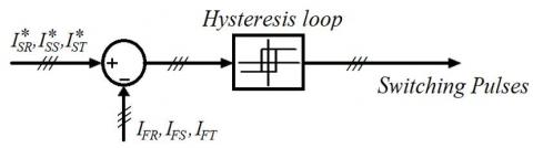
Figure 2. The hysteresis band current control
Consider Figure 2, the use of hysteresis band current control methods for active power filters is used to detect the line current from the three-phase system supplied to the non-linear load, which is defined as the error current occurring in the system. The error current received is caused by the removal from the actual filter current in the three-phase system with the reference current. The reference current used is derived from phase current waveform the three-phase system, which is expressed as ISR*, ISS*, IST*. Consequently, the actual filter current is IFR, IFS, IFT, which sends an error signal to the loop hysteresis to create a PWM for the switch device that is an inverter.
Figure 3. A magnified depiction of the hysteresis current control
Figure 3 is the magnified depiction of a section of the hysteresis current control, where the curve line and the dash lines above and underneath respectively represent the reference current and the upper and lower limits. Which describes the principle of tracking the lower and upper band of the hysteresis current from the reference current of single-phase systems [16].
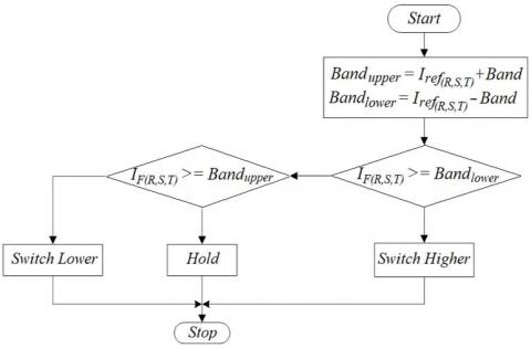
Figure 4 diagram showing the hysteresis current control for PWM signal modulation for the control of all six IGBT switch devices adopted as shunt active power filter mechanisms.
Figure 4. Flowchart diagram of the hysteresis current control
2.3 PID control system
Mathematically, the PID controller has mathematical operations proportional, integral, and derivative. The mathematical relation signals of these controllers consist of e(t) which is the input signal and u(t) is the output signal as Eq. (1). Where Kp is the proportional gain constant, Ki is the integral gain constant and Kd is derivative gain constant. Consequently, the transfer function Gc(s) of the PID controller is given in Eq. (2).
$u(t)=K_{P} e(t)+K_{i} \int e(t) d t+K_{d} \frac{d e(t)}{d t}$ (9)
$\left.G_{c}(s)\right|_{P I D}=K_{P}+\frac{K_{i}}{s}+K_{d} s=\frac{K_{d} s^{2}+K_{p} s+K_{i}}{s}$ (10)
$\left.G_{c}(s)\right|_{P I D}=K_{c}\left(1+\frac{1}{\tau_{i} s}+\tau_{d} s\right)$ (11)
In addition, the transfer function Gc(s) of PID controllers may be shown as Eq. (11), where ti is integral time constant and td is derivative time constant. When comparing the Eqns. (10) and (11), it is found that
$K_{P}=K_{c}$
$K_{i}=K_{c} / \tau_{i}$
$K_{d}=K_{c} \tau_{d}$ (12)
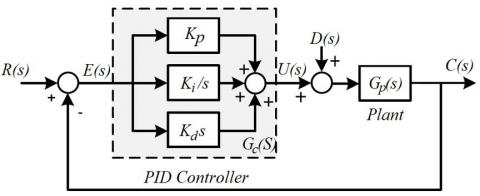
Consider the control system Figure 5, the controller of PID, Gc(s) will receive an error signal (E(s)) to calculate to produce control signal (U(s)) and control the plant (Gp(s)) to produce the response or output signal (C(s)) consistent with the reference input signal (R(s)) with arrange disturbance signal (D(s)) along the way. The PID controller has one pole at the origin and two at zero, when the controller PID is positioned forward path of control the loop is connected in series with the plant, which has a function of Gp(s). Consequently, control systems controlled by PID controllers will have one more order.
Figure 5. PID control diagram
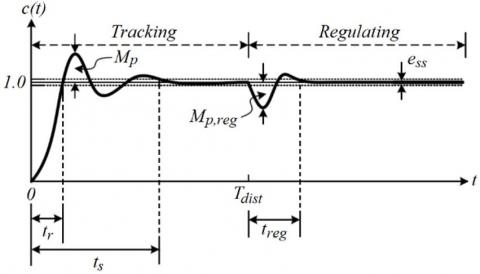
Nevertheless, the system response in the time domain can be divided into command following/tracking response and load response regulating as in Figure 6. The effect of tuning the parameters of the PID controller on the system response in the time domain can be summarized in Table 1. When tr is rise time, Mp is maximum overshoot, ts is settling time, Mp,reg is maximum overshoot of load regulation, treg is settling time of load regulation and ess is steady-state error.
Figure 6. System response in the domain
From Table 1, the reason for this research is based on the PI control principle, because the kp, ki adjustment makes the tuning of the control system applied to the mechanism of the device being created. For a controlling kd from that Table 1 will find that the interval tr changes slightly, although the Mp and tr decreases, but does not affect the mechanism of the device created.
Table 1. Effect of parameter adjustment of PID controller
|
parameter |
tr |
Mp |
ts |
ess |
|
Kp |
Decrease |
Increase |
Little change |
Decrease |
|
Ki |
Decrease |
Increase |
Increase |
Was eliminated |
|
Hd |
Little change |
Decrease |
Decrease |
No effect |
2.4 Design of PI controllers
The transfer function of the PI controller for this research is defined as
$\left.G_{c}(s)\right|_{P I}=K_{p}+\frac{K_{i}}{s}$ (13)
Figure 7, using PI for controlling the DC-link voltage of the prototype device created, it will set the amplitude rating of the current used for the shunt active power filter, to control the capacitor's voltage (DC- link) according to the amplitude of the reference current that covers the inverter loss too. The proportional gain adjustment is derived using Kp = 2xwnC for the dynamic response of the capacitor voltage control. Similarly, the adjustment of integral gain is derived using Ki = Cwn2 to determine the appropriate response time. When compared to the measured load current, the result is the reference current of the shunt active power filter. This reason, the determination of Kp and Ki determines ξ = 0.707 and C = 1100 × 10-6 F.
Figure 7. Diagram of PI controllers
Nevertheless, a win-up integral control that is a phenomenon of impulse signals in saturated conditions in a closed-loop control system, resulting in the impulse not being able to respond to the signals from the controllers in a short time, causes the control system to take the time to enter the settling point lasts longer and causes overshoot. For this research, take into consideration the tuning until the input and output signals are at an appropriate level. However, most win-up integration systems are slow to respond, resulting in many discrepancies, causing the signal to fluctuate for a period of time.
2.5 Power factor control
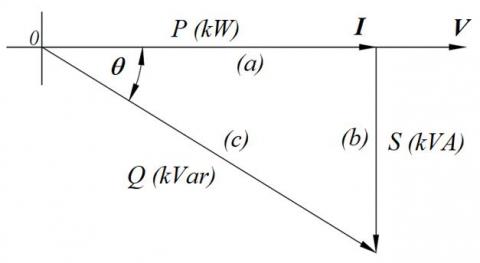
The waveform, current and voltage sinusoidal waveforms with the shift-phase is a method that can be used to determine the power factor of the system. This power factor is an indicator of the characteristics of each type of load in the electrical system. For example, if the shift-phase current waveform is lagging the voltage waveform, that is an inductive load type. Nevertheless, when considering the trigonometric power, it is found that there are three components of the electric power: the apparent power (S), the active power or real power (P), the reactive power (Q) as in Figure 8. When writing trigonometric equations as
$c^{2}=a^{2}+b^{2}$ (14)
$c=\sqrt{a^{2}+b^{2}}$ (15)
Figure 8. The trigonometric function
From the trigonometric equation, when written into the apparent power equation is
$k V A=\sqrt{k W^{2}+k V a r^{2}}$ (16)
Similarly, if considering the relationships of power factors in the system can be written as
$P F=\left(\frac{k W}{k V a r}\right)=\cos ^{-1} \theta$ (17)
From the Eq. (17), it is found that the power factor is the amplitude of the angle θ, is the angle between voltage and current which may be lagging or leading. Consequently, it can be concluded that the power factor is more or less the result of the load connected to the electrical system and when using the theory of trigonometry.
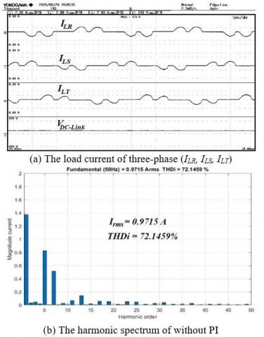
Figure 9(a) and (b) when the power transmission system provides non-linear loads with MATLAB/Simulink control functions through TMS320F28335 DSP microcontrollers while there is without PI function control. Nevertheless, the prototype device can detect a small amount of the current supplied to the non-linear load, which makes it possible to detect the 5th, 7th, 9th, and the 11th harmonic spectrum, resulting in the attenuation mechanism harmonics in power transmission systems with low efficiency.
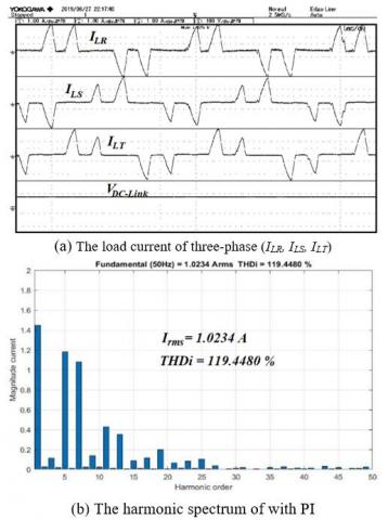
Consider Figure 10(a) the result of the non-linear load supplied with PI control function. It finds that the prototype device which can detect, a large amount of current that is supplied to the load. Figure 10 (b) resulting in the 5th, 7th, 9th and the 11th harmonic spectrum as well.
Figure 9. The power transmission system supply non-linear load without PI
Figure 10. The power transmission system supply non-linear load with PI
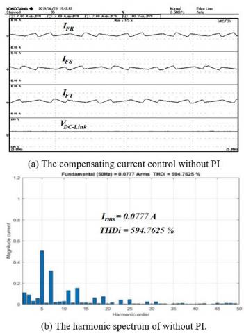
Figure 11. The function without PI control
Figure 12. The function with PI control
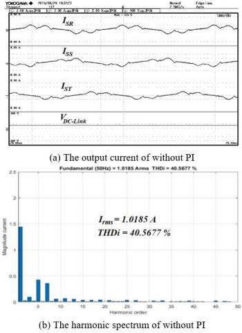
Figure 13. The output current of power transmission system without PI control
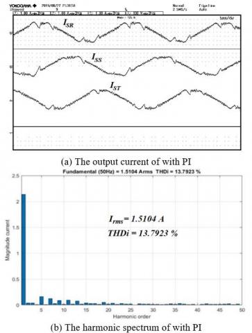
Figure 14. The output current of the power transmission system with PI control
Figure 11(a) the result of the compensating current control from the mechanism of the prototype device shows that the function without PI control provides less power than the function with PI. Figure 11(b) the results of the harmonic spectrum correspond to the load current. Moreover, the DC link voltage across the capacitor can also be controlled to have a constant voltage and a large quantity when it is a PI function. Figure 12(a) and (b) the results are satisfactory, consistent with the load current and according to theory.
Figure 13(a) and (b) shows that the output current in the power transmission system without PI control functions is consistent and relevant to the load current and the compensating current. Accordingly, the result of a function with PI can control the compensation current so that the system is stable and reduces harmonic currents more than there is without PI control function as in Figure 14 (a) and (b).
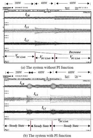
Figure 15 (a) and (b) shows the results of the mechanism of the prototype device when the non-linear load is rapidly increased to a step, adding non-linear loads 200W, 400W and 600W to test the detection of load currents and test the tracking of compensating currents accordingly controlling the DC link voltage across the capacitor. It was found that the results of the prototype engine were satisfactory. When considering the DC link voltage across the capacitor, it is found that the system with PI function can effectively control the DC link voltage, resulting in the apparent power (S), the real power (P) and the reactive power (Q) according to the principle of trigonometry.
Figure 15. The non-linear load is rapidly increased to a step
Table 2. Comparison of relationships between PI control and without PI control
|
Condition |
PI control |
Without PI control |
|
Voltage/phase (V) |
32.94 |
31.86 |
|
Current/phase (A) |
1.54 |
1.04 |
|
Apparent power (kVA) |
0.051 |
0.033 |
|
Real power (kW) |
0.043 |
0.024 |
|
Reactive power (kVar) |
0.028 |
0.023 |
|
Power factor (Cos q) |
0.84 |
0.73 |
Table 2 results from the power analyser (WT500) of YOKOGAWA, the mechanism of the prototype device with the PI function and without the PI function, when comparing, it is found that the function with PI can provide satisfactory control of the power and results in the angle of the power factor nearly unity.
The efficiency enhancement of shunt active power filtering with PI control in three-phase three-wire system. The advantage of a prototype mechanical device that can be clearly shown is that when tested by connecting the mechanism into the electrical system, it can reduce the harmonic occurrence due to the nonlinear load resulting in the power in the electrical system to increase. Nevertheless, the prototype device has limitations causing disadvantages due to the size and rating of the voltage and current detector, the size of the capacitor and the limitations of the TMS320F28335 DSP microcontrollers etc.
This research, optimization of active power filtering with PI control in three-phase three-wire system. The created a prototype mechanism for detecting the current supplied to the non-linear load and the compensation current tracking control, so that the current in the power transmission system can provide stable non-linear loads and reduce the harmonic currents that occur in the power. The results are satisfactory and can confirm that the control using PI function can increase the efficiency of the power transmission system for the purpose. Nevertheless, it can be seen that the parallel power filter active filter mechanism still cannot control the individual harmonic at a bus voltage less than 1kV (PCC), resulting in harmonic in the 5th order is not yet finished to the standard IEEE STD 519-2014. Moreover, also resulting in total harmonic distortion higher than the standard set.
Consequently, in the next development, the researchers agreed that the development of mechanical devices that can reduce the 3rd, 5th, 7th, and 9th harmonic devices should be reduced or disappeared. The device is a hybrid filter consisting of a shunt active filter and passive power filter, allowing users to transmit power at a bus voltage below 1kV able to distribute loads efficiently and in accordance with the established standards. As a result, users can save and reduce their business expenses.
Dhonburi Rajabhat University, Thailand supported this event. The author would like to thank Mr. Kritsada Tunta and a technical working group to test the prototype device created and Mr. Sakdawut boontua for setting up the experiment to accomplish this research.
|
P |
Real power |
|
Q |
Reactive power |
|
S |
Apparent power |
|
I |
Electric current |
|
V |
Electric voltage |
|
PWM |
Pulse width modulation |
|
THD |
Total harmonics distrotion |
|
PI |
Proportional-Integral Controller |
|
PID |
Proportional-Integral-Derivative Controller |
|
IGBT |
Isolate Gate Bipolar Transistor |
|
PCC |
Point of common coupling |
|
Subscripts |
|
|
SR |
Phase sequence R of three phase system |
|
SS |
Phase sequence S of three phase system |
|
ST |
Phase sequence T of three phase system |
|
FR |
Compensated current of Phase sequence R |
|
FF |
Compensated current of Phase sequence S |
|
FT |
Compensated current of Phase sequence T |
|
LR |
Load current of Phase sequence R |
|
LS |
Load current of Phase sequence S |
|
LT |
Load current of Phase sequence T |
[1] Ismail, G., Toufik, B.M., Said, B. (2018). Real time implementation of feedback linearization control based three phase shunt active power filter. European Journal of Electrical Engineering, 20(4): 517-532. https://doi.org/10.3166/EJEE.20.517-532
[2] Abdelmadjid, C., Jean-Paul, G.F.K., Laurent, R. (2006). IP controlled three-phase shunt active power filter for power improvement quality. IEEE Industrial Electronics,IECON IECON 2006. https://doi.org/10.1109/IECON.2006.348043
[3] Sabir, O., Achour, B., Jean-Paul, G. (2017). Simulation and real time implementation of predictive direct power control for three phase shunt active power filter. Simulation Modelling Practice and Theory, 78: 1-17. https://doi.org/10.1016/j.simpat.2017.08.003
[4] Liu, L., Wang, S.T. (2019). Improving low voltage ride-through with STATCOM and SDBR for wind turbine with squirrel-cage induction generator. European Journal of Electrical Engineering, 21(2): 179-187. https://doi.org/10.18280/ejee.210208
[5] Muyeen, S.M. (2015). A combined approach of using an SDBR and a STATCOM to enhance the stability of a wind farm. IEEE Systems Journal, 9(3): 922-932. https://doi.org/10.1109/JSYST.2013.2297180
[6] Chaithanakulwat, A., Kinnares, V. (2017). Implementation of a low-cost single-phase grid-connected photovoltaic system with active power filtering mechanism. International Review of Electrical Engineering (IREE), 12: 175-182. https://doi.org/10.15866/iree.v12i2.11383
[7] Chaithanakulwat, A. (2019). Multi-functionality control, power filtering single-phase grid-connected photovoltaic system. American Journal of Electrical Power and Energy Systems, 8(2): 62-70. http://doi.org/10.11648/j.epes.20190802.14
[8] Chaithanakulwat, A. (2019). Track the maximum power of a photovoltaic to control a cascade five-level inverter a single-phase grid-connected with a fuzzy logic control. International Journal of Power Electronics and Drive Systems (IJPEDS), 10(4): 1863-1874. http://doi.org/10.11591/ijpeds.v10.i4
[9] Chaitanakulwat, A., Kinnares, V., Thungsuk, N. (2012). Single-phase grid-connected photovoltaic system with active power filter functionality. In 2012 15th International Conference on Electrical Machines and Systems (ICEMS). pp. 1-3.
[10] Chaithanakulwat, A. (2020). Development of DC voltage control from wind turbines using proportions and integrals for Three-phase grid-connected inverters. International Journal of Electrical and Computer Engineering (IJECE), 10(2): 1701-1711. http://doi.org/10.11591/ijece.v10i2
[11] Zou, T., Geng, H., Wang, K. (2016). Optimized harmonic detecting and repetitive control scheme for shunt active power filter in synchronous reference frame. 2016 IEEE 8th International Power Electronics and Motion Control Conference (IPEMC-ECCE Asia), pp. 680-684. http://doi.org/10.1109/IPEMC.2016.7512367
[12] Singh, B., Dube, S.K., Arya, S.R. (2015) An improved control algorithm of DSTATCOM for power quality improvement. International Journal of Electrical Power & Energy Systems, 64: 493-504. https://doi.org/10.1016/j.ijepes. 2014.07.055
[13] Hogan, D.J., Gonzalez-Espin, F.J., Hayes, J.G., Lightbody, G., Foley, R. (2017). An adaptive digital-control scheme for improved active power filtering under distorted grid conditions. IEEE Transactions on Industrial Electronics, 65(2): 988-999. https://doi.org/10.1109/ TIE.2017.2726992
[14] Cao, W., Wu, M., Zhao, J., Liu, W., Lu, Y. (2018). An improved current-limiting strategy for shunt active power filter (SAPF) using particle swarm optimization (PSO). 2018 IEEE Applied Power Electronics Conference and Exposition (APEC), pp. 494-498. https://doi.org/10.1109/APEC.2018.8341057
[15] Adam, M., Chen, Y.P., Deng, X.T. (2018). Harmonic current compensation using active power filter based on model predictive control technology. Journal of Power Electronics, 18(6): 1889-1900.
[16] Chaithanakulwat, A. (2019). Design of solar-powered aeration system for shrimp ponds of farmers in Thailand. European Journal of Electrical Engineering, 21(6): 539-546. https://doi.org/10.18280/ejee.210608