Dadabaev Shakhboz Tolibjonovich* | Toshkhodzhaeva Muhayo Islomovna | Mirkhalikova Dilafruz Saidulloevna
© 2020 IIETA. This article is published by IIETA and is licensed under the CC BY 4.0 license (http://creativecommons.org/licenses/by/4.0/).
OPEN ACCESS
Asynchronous machines are widely used in various industrial machines and devices. These engines are reliable and easy to use. In developed countries AC electric drives with asynchronous machines consume approximately 60% of the total electricity generated. Therefore, research in this direction is considered an urgent and highly demanded task. The article considers the main advantages and disadvantages of asynchronous machines, analyzes the starting negative factors of asynchronous machines, conducts computer simulation of the starting regimes of asynchronous machine with redused voltage network, clearly shown the simulation results of the main parameters of asynchronous machines as speed, current and electromagnetic torque. Also the result of simulation shown mechanical characteristics of the asynchronous machine at redused voltage supply network. The main research methods in this scientific work were carried out by means of mathematical and computer modeling, and more precisely with the help of the MATLAB program. The novelty of the article is a deep analysis of the influence of the mains voltage on the parameters of the asynchronous machine and the determination of the exact critical values of the mains voltage at which the start of the asynchronous machine will be impossible.
reduced voltage, power quality, asynchronous machines, MATLAB, computer simulation, starting transients, mechanical characteristic
Previously, only DC electric drives were taken as the basis of regulating electric drives and AC electric drives with asynchronous and synchronous motors remained uncontrollable. This circumstance was explained by the difficulties in regulating the speed of rotation of asynchronous machines, as well as complex and difficult transients that occur during transient modes of operation of AC motors [1]. Asynchronous machines are widely used in various sectors of the national economy, for example, asynchronous electric motors of high power are used in turbomechanisms, such as pumps, compressors, fans etc. [2]. Asynchronous low-power machines are used in various machine tools and mechanisms, such as metal cutting machines, spinning machines, etc. [3]. A distinctive feature of asynchronous machines is the complex starting modes of operation, where the starting currents can be up to 7In, and the starting electromagnetic torque up to 3Mn [4]. Starting currents can lead to heating and loss of stability winding insulation, and thereby reducing the life of all electrical equipment as a whole. The working temperature a part of the electrical equipment depends not only on the load, but also depends from the temperature of the environment too [5]. The elimination of negative starting factors in asynchronous machines can be achieved using soft start systems (soft starter) or using frequency converters [6]. Other features of asynchronous motors include the relationship of machine parameters with the mains supply [7]. For example, a direct start of asynchronous motors is permissible if its start does not lead to a voltage failure of no more than 10%, and the dependence of the electromagnetic moment and voltage of the supply network in asynchronous machines is squarely directly proportional [8]. For a more detailed study of the operating modes of asynchronous motors at different values of the voltage network, it is necessary to perform computer simulation. For perform this task, in first necessary to analyze the mathematical model of asynchronous machine [9-11].
The contribution of the article largely can be considered theoretical laws and knowledge, but the results obtained are also applicable to practice. Therefore, for example, based on the results obtained, it is possible to correctly and optimally select starting electric equipment for electric drives. Moreover, possible continue research in this direction and start mass production of special asynchronous machines that can work well with low quality electricity [12]. Such machines will primarily be intended for countries where to the quality of electricity does not provide the necessary attention, and their main task is to supply people with electricity, albeit with low quality.
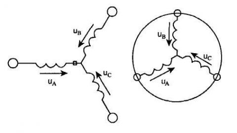
The generalized asynchronous machine contains a three-phase winding on the stator and rotor, which are connected to symmetrical three-phase voltage sources, example shown in Figure 1 [11, 13].
The equations of equilibrium of electromotive force on the stator and rotor windings of asynchronous machine have the next form [11, 14, 15]:
For stator
$u_{A}=R_{A} i_{A}+\frac{d \Psi_{A}}{d t}$,
$u_{B}=R_{B} i_{B}+\frac{d \Psi_{B}}{d t}$, (1)
$u_{C}=R_{C} i_{C}+\frac{d \Psi_{C}}{d t}$.
For rotor
$u_{a}=R_{a} i_{a}+\frac{d \Psi_{a}}{d t}$,
$u_{b}=R_{b} i_{b}+\frac{d \Psi_{b}}{d t}$, (2)
$u_{c}=R_{c} i_{c}+\frac{d \Psi_{c}}{d t}$.
Figure 1. Generalized asynchronous machine
Eqns. (1)-(2) feature instantaneous voltages, currents and flux linkages of the stator and rotor, as well as the active resistances of the windings. Typically, the windings are symmetrical, and therefore RA = RB = RC = RS is the active resistance of the stator winding, Ra = Rb = Rc = Rr is the active resistance of the rotor winding [16-18].
In asynchronous machines, the induction flux of the stator and rotor windings with their currents are described by the following equations:
For stator
$\Psi_{A}=L_{A A} i_{A}+L_{A B} i_{\mathrm{B}}+L_{A C} i_{C}+L_{A a} i_{a}+L_{A b} i_{b}+L_{A c} i_{c}$,
$\Psi_{B}=L_{B A} i_{A}+L_{B B} i_{\mathrm{B}}+L_{B C} i_{C}+L_{B a} i_{a}+L_{B b} i_{b}+L_{B c} i_{c}$, (3)
$\Psi_{C}=L_{C A} i_{A}+L_{C B} i_{\mathrm{B}}+L_{C C} i_{C}+L_{C a} i_{a}+L_{C b} i_{b}+L_{C c} i_{c}$.
For rotor
$\Psi_{a}=L_{a A} i_{A}+L_{a B} i_{\mathrm{B}}+L_{a C} i_{C}+L_{a a} i_{a}+L_{a b} i_{b}+L_{a c} i_{c}$,
$\Psi_{b}=L_{b A} i_{A}+L_{b B} i_{\mathrm{B}}+L_{b C} i_{C}+L_{b a} i_{a}+L_{b b} i_{b}+L_{b c} i_{c}$, (4)
$\Psi_{c}=L_{c A} i_{A}+L_{c B} i_{\mathrm{B}}+L_{c C} i_{C}+L_{c a} i_{a}+L_{c b} i_{b}+L_{c c} i_{c}$.
From Eqns. (3)-(4) it is seen that the induction flux of asynchronous machine (AM) depends from the currents of the windings [11, 19]. The equations for determining the flux linkage show that the flux linkage of each winding depends on the currents in all windings; these dependences are manifested through mutual induction. In Eqns. (3)-(4), LAA, LBB, LCC, Laa, Lbb, Lcc are the intrinsic inductances of the corresponding windings, all the others are the mutual inductances between the corresponding windings [20-22].
The equation of motion of the machine is described by the following differential equations:
$J \frac{d \omega_{m}}{d t}=M-M_{c}$ (5)
where, J is the inertia of AM (kg⋅m2), ωm is the rotation speed of AM (rad/s), M and Mc are the torques of AM and mechanism (N⋅m).
For completeness, it is necessary to use a law that serves to bind the vector values of the moment, flux linkage and current. This is Lenz’s law that has the following form:
$\vec{M}=k(\vec{\Psi} \times \vec{i})$ (6)
Note that, despite the full and rigorous mathematical description, the use of Eqns. (1)-(6) for the study of the machine has serious difficulties [23, 24]. To solve such complex problems today, various computer programs are widely used that can simplify the process of mathematical calculations or solving equations [25, 26].
For computer simulation of asynchronous machine, was used the MATLAB program. The modeling process of asynchronous machine in the MATLAB program is more described in the following references [15, 16]. For simulation was selected asynchronous machine series RA112M4 with squirrel-cage rotor type. Machine technical data are given in Table 1.
Table 1. Technical parameters of asynchronous machine
|
Parameter Name |
Passport Parameters |
The Calculated Parameters |
|||
|
Values |
Units |
Values |
Units |
||
|
Power, Pn |
4000 |
W |
|
|
|
|
Revolution per minute |
1430 |
rpm |
|
|
|
|
The efficiency of AM |
85.5 |
% |
|
|
|
|
cosφ |
0.84 |
|
|
|
|
|
Current, Inom |
9 |
A |
|
|
|
|
Ik/Inom |
6.5 |
|
|
|
|
|
Mk/Mnom |
2.2 |
|
|
|
|
|
Mmax/Mnom |
2.9 |
|
|
|
|
|
Inertia |
0.0103 |
kg⋅m2 |
|
|
|
|
Nominal voltage |
380 |
V |
|
|
|
|
Frequency, fn |
50 |
Hz |
|
|
|
|
Pole pairs, p |
2 |
|
|
|
|
|
Stator |
resistance, Rs |
|
|
0.5006 |
Ohm |
|
inductance, Ls |
|
|
0.00589 |
H |
|
|
Rotor |
resistance, Rr |
|
|
0.9289 |
Ohm |
|
inductance, Lr |
|
|
0.00589 |
H |
|
|
Mutual inductance, Lm |
|
|
0.2031 |
H |
|
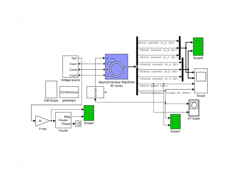
Figure 2. Computer model of asynchronous machine
An adapted model for studying the starting modes of asynchronous machine at a reduced voltage is shown in Figure 2.
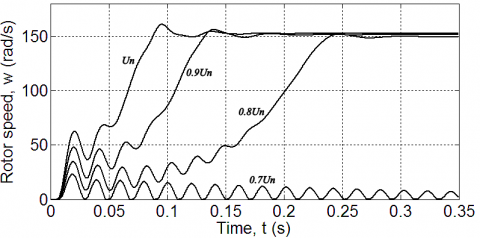
Using computer model, we can analyze the behavior of asynchronous machine when the network voltage Un is reduced. One of the main parameters of electric motors is its speed and the rotation speed of the asynchronous machine (AM), that shown in Figure 3 in reduced voltage.
Figure 3. Transient graphs of the speed of AM
As can be seen in Figure 3, the more we reduce the rated mains voltage Un, the longer the start-up of an asynchronous machine is delayed. As can be seen in Figure 3, the more we reduce the rated voltage Un, the longer the delay in starting an asynchronous machine last. It also became known that the motor speed when the voltage was reduced by 10%, the start time increased by 33%, and when the mains voltage decreased by 20%, the start time of the asynchronous machine increased by 100% and amounted to 0.3 s, which is two times more than at the rated value of the mains voltage.
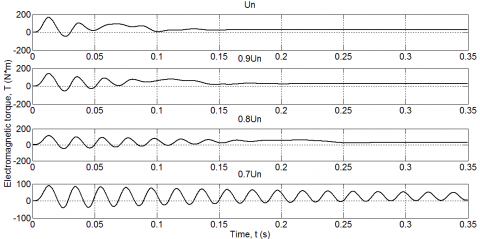
As we see, when starting with reduce voltage, the speed of the AM slowly picks up acceleration than with a nominal voltage value. As already noted, the electromagnetic torque of AM is directly proportional to the supply voltage. Transient graphs of the electromagnetic torque of AM are shown in Figure 4.
Figure 4. Transient graphs of the torque of AM in different voltage values: Un; 0.9Un; 0.8Un; 0.7Un
Figure 4 shows how the torque of an asynchronous machine behaves at a reduced network voltage. In accordance with the obtained graphs, we can conclude that the torque and voltage are directly proportional. And at a voltage of 0.7Un, the engine torque cannot go into a static mode of operation.
Transient graphs of currents of AM are shown in Figures 5-8.
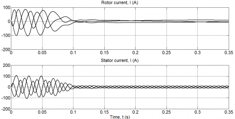
Figure 5. Transient graphs of the rotor and stator currents of AM in Un
Figure 5 shows how the rotor and stator currents of an asynchronous machine behave at the rated mains voltage. As it became known, the rotor and stator currents during startup of an asynchronous machine increased sharply and then decreased to nominal values in a short time of the transition process.
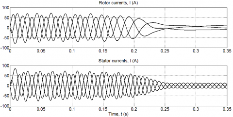
Figure 6. Transient graphs of the rotor and stator currents of AM in 0.9Un
Figure 7. Transient graphs of the rotor and stator currents of AM in 0.8Un
Figures 6 and 7 show how the rotor and stator currents of an asynchronous machine change with a decrease in the network voltage by 0.9Un and 0.8Un. According to the graphs, it can be seen that when the network voltage decreases by 10% and 20%, the transient time increased from 0,1 s to 0.15 and 0.25 s, respectively. And also the amplitude of the rotor and stator currents decreased in significant values.
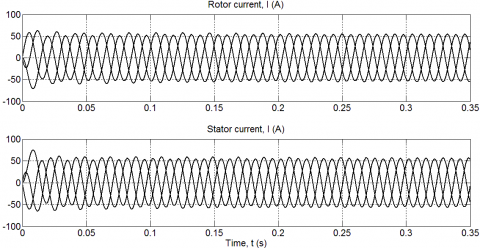
Figure 8. Transient graphs of the rotor and stator currents of AM in 0.7Un
Figure 8 shows that when the mains voltage decreases by more than 30%, the rotor and stator currents cannot cope with the static load and continuously change with the starting value to switch to normal operation. But with such a low mains voltage, the engine does not have enough torque and rotation speed in order to enter the operating mode and the engine fast starts to heat up very much.
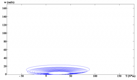
As shown by the transient graphs of the torque and current of AM, these machine parameters directly depend on the network voltage. Mechanical characteristics of AM are shown in Figures 9-12.
Figure 9. Mechanical characteristic of AM in Un
Figure 10. Mechanical characteristic of AM in 0.9Un
Figure 11. Mechanical characteristic of AM in 0.8Un
The mechanical characteristics in Figures 9 - 11 shows that the engine torque, when the mains voltage decreases, begins a sharp change with a variable sign and thereby may cause vibration and additional noise in the AM.
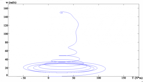
Figure 12. Mechanical characteristic of AM in 0.7Un
The mechanical characteristic of an asynchronous machine according to Figure 12 shows that when starting with a 30% lower voltage, the asynchronous machine will not start. The speed will not reach the required value and the engine torque remains high and alternating, which can lead to overheating and additional engine vibrations.
According to the simulation results (Figure 3-12), at starting AM with a reduced voltage network, the following conclusions can be drawn:
The simulation results are significantly different from other works on this topic, the fact is that before that a detailed analysis was not introduced and the studies were generalized and not detailed, or narrow on this problem. Patterns and theoretical knowledge, and the results obtained are consistent with other scientific works carried out earlier by other scientists and therefore the reliability of the results should not be in doubt. The specific results of the study include detailed graphs of transients of the parameters of an asynchronous machine with non-standard operating modes, as with a reduced network voltage, i.e. with poor quality mains voltage.
[1] Dadabaev, S.T. (2019). Simulation of soft start of synchronous electric drives. CAD/EDA, Modeling and Simulation in Modern Electronics: collection of scientific papers of the III International Scientific and Practical Conference, pp. 140-145. http://dx.doi.org/10.30987/conferencearticle_5e0282116891e4.18084453
[2] Dadabaev, S.T. (2018). Optimization of starting modes of high-voltage electric drives of irrigation pumping station in hot climate. Russian Electromechanics, 6(2): 86-91. (In Russ). http://dx.doi.org/10.17213/0136-3360-2018-2-86-91
[3] Dadabaev, S.T. (2017). Modelirovanie rezhimov puska vysokovol''tnogo sinkhronnogo elektroprivoda s ustroystvom plavnogo puska [Modeling starting modes of a high voltage synchronous electric drive with a smooth start device]. V sbornike: SAPR i modelirovanie v sovremennoy elektronike. Sbornik nauchnykh trudov I Mezhdunarodnoy nauchno-prakticheskoy konferentsii. Pod red. L.A. Potapova, A.Yu. Drakina. Bryansk, pp. 91-94. (In Russ).
[4] Dadabaev, S.T., Dadabaeva, Z.A. (2018). Komp''yuternoe modelirovanie sposobov puska elektroprivodov s ventilyatornoy nagruzkoy [Computer simulation of ways to start electric drives with fan load]. V sbornike: Elektroprivod na transporte i v promyshlennosti trudy II Vserossiyskoy nauchno-prakticheskoy konferentsii, pp. 323-327. (In Russ)
[5] Bruce, F.M., Graefe, R.J., Lutz, A., Panlener, M.D. (1984). Reduced-voltage starting of squirrel-cage induction motors. IEEE Transactions on Industry Applications, IA-20(1): 46-55. http://dx.doi.org/10.1109/TIA.1984.4504374
[6] Aree, P. (2016). Starting time calculation of large induction motors using their manufacturer technical data. 2016 19th International Conference on Electrical Machines and Systems (ICEMS), Chiba, pp. 1-5.
[7] Nevelsteen, J., Aragon, H. (1989). Starting of large motors – methods and economics. IEEE Transactions on Industry Applications, 25(6): 1012-1018. http://dx.doi.org/10.1109/28.44236
[8] Cazacu, E., Petrescu, L. (2014). Magnetizing inrush current of low-voltage iron core three phase power reactors. 16th International Conference on Harmonics and Quality of Power (ICHQP), Bucharest, pp. 843-847.
[9] Chapman, S. (2011). Electric Machinery Fundamentals. Mcgraw Hill Higher Education, 5th Edition.
[10] Krause, P.C., Wasynczuk, O., Sudhoff, S., Pekarek, S. (2013). Analysis of Electric Machinery and Drive Systems. Wiley-IEEE Press, 3rd Edition. http://dx.doi.org/10.1002/9781118524336
[11] Terekhin, V.B. (2008). Modelirovanie sistem elektroprivoda v Simulink (Matlab 7.0.1) [Simulation of electric drive systems in Simulink (Matlab 7.0.1)]: uchebnoe posobie /V.B. Terekhin. – Tomsk: Izd-vo Tomskogo politekhnicheskogo universiteta. (In Russ)
[12] Mirkhalikova, D.S., Azimov, N.S. (2019). Vliyanie kachestva elektroenergii na rabotu nasosnykh stantsiy [Influence of quality of electric power on the work of pumping stations]. Izvestiya Tul'skogo gosudarstvennogo universiteta. Tekhnicheskie nauki, (12): 210-213. (In Russ).
[13] German-Galkin, S.G., Kardonov, G.A. (2003). Elektricheskie mashiny: Laboratornye raboty na PK [Electric machines: Lab work on a PC.]. – SPb.: KORONA print. (In Russ).
[14] Chernikh, I.V. (2008). Modelirovanie elektrotekhnicheskikh ustroystv v MATLAB, SimPowerSystema i Simulink [Modeling of electrical devices in MATLAB, SimPowerSystema and Simulink]. – M.: DMK Press; SPb.: Piter. (In Russ).
[15] Mathworks, SimPowerSystems. User’s Guide, 2010-2017.
[16] Mathworks, SimPowerSystems, User’s Guide, Natick MA.
[17] Krause, P.C., Wasynczuk, O., Sudhoff, S.D. (2002). Analysis of Electric Machinery. IEEE Press. Piscataway NJ. 2002.
[18] Wu, X.Q., Steimel, A. (1997). Direct self control of induction machines fed by a double three-level inverter. IEEE Transactions on Industrial Electronics, 44(4): 519-527. http://dx.doi.org/10.1109/41.605629
[19] Bose, B.K. (2006). Advances and trends in power electronics and motor drives. Elsevier. Amsterdam the Netherlands.
[20] Filho, E., de Souza, R. (1997). Three-phase induction motor dynamic mathematical model. IEEE International Electric Machines and Drives Conference Record, pp. MB1/2.1-MB1/2.3. http://dx.doi.org/10.1109/IEMDC.1997.604070
[21] Holtz, J. (1994). The induction motor a dynamic system. 20th International Conference on Industrial Electronics, Control and Instrumentation, 1: P1-P6. http://dx.doi.org/10.1109/IECON.1994.397757
[22] Hughes, A., Drury, B. (2013). Electric Motors and Drives: Fundamentals. Types and Applications 4th ed. Elsevier.
[23] Lorenz, R.D., Lipo, T.A., Novotny, D.W. (1994). Motion control with induction motors. Proceedings of the IEEE, 82(8): 1215-1240. http://dx.doi.org/10.1109/5.301685
[24] Ong, C.M. (1998). Dynamic Simulation of Electric Machinery Using MATLAB. Prentice Hall.
[25] Leonhard, W. (2001). Control of Electrical Drives. 3rd ed. Springer. http://dx.doi.org/10.1007/978-3-642-56649-3
[26] El-Hawary, M. (2002). Principles of Electric Machines with Power Electronic Applications. IEEE Press. http://dx.doi.org/10.1109/9780470545645