Gaddala Jayaraju* | Gudapati Sambasiva Rao
OPEN ACCESS
A novel topology of Single phase grid connected system based on photo voltaic system through high gain single switch DC-DC Luo converter is proposed in this paper. In this novel topology the single phase grid connected to PV-Wind system followed by Luo converter and single phase voltage source inverter. The PV system voltage fluctuation problems are overcome by maximum power point tracking algorithm. The new optimized Artificial Neural Network technique (ANN) is used. It extracts the maximum power from the PV system. To compare the conventional schemes the proposed topology is modeled with the help of reference frames includes direct axis and quadrature axis elements. The LUO converter inherits the advantages compared to other DC-DC to converter topologies. The ANN based MPPT algorithm shows excellent performance under various testing conditions and the outcomes are differentiated with P&O algorithm and Fuzzy based MPPT algorithm. The PWM generators are used to trigger the inverter and LUO converter. Steady state and transient response of the controllers are discussed and implement the excellent operation of the PV fed energy system. The grid current synchronization is achieved by using PI controller also reduces the THD and satisfies the IEEE harmonics standard. The proposed system reduces the power quality issues in the PV based single phase grid connected system.
distributed generation, PV system, PMSG, Luo converter, Fuzzy MPPT algorithm, ANN algorithm
Distribution energy generation system based on non conventional energy resources, i.e. PV system and Wind generation system is playing the main contribution for green energy generation. But from the PV system, oscillatory output voltage and discontinuous input current operation is acquired, it includes higher level ripple contents and partial shading effect. From the wind power, the Permanent magnet Synchronous generator converts mechanical energy into three phase electrical energy [1]. The PMSG output is not constant, it has higher order harmonics due to Permanent Magnet and oscillations in nature.
The authors Esram and Chapman, Fang and Xu, and Femia et al. [2-4] discussed a few MPPT strategies taken from the writing and investigated with their advantages and disadvantages. It is difficult to choose the better option with the available so many MPPT techniques. The important aspects to be considered while selecting particular algorithm are the ease of implementation, number of sensors required, the occurrence of multiple local maxima, monetary costs and area of application. But the distributed generation requires constant power and voltage operation. In order to attain constant high power operation DC-DC converter is used. In existing topologies transformer based grid connected PV systems are used. This transformer is of high cost and increases the leakage reactance problems. Also it requires galvanic isolation. The DC-DC Boost converters are used to overcome the transformer based grid connected distribution system. This boost converter topology maintains continuous input current operation and single frequency output ripple suppression. The different MPPT algorithms are used to maintain constant voltage operation. In boost DC-DC converter only boost operation is possible. Also low output voltage gain with higher order ripple contents. Buck-boost converter overcomes the drawbacks of existing boost converter. Buck-boost converters does both buck and boost operation with single order frequency suppression in the output voltage but these converters experiences discontinuous input current operation. This increases the switching loss and reduces the performance of the system.
A theoretical input-parallel output parallel (IPOP) DC-DC converter with MPPT method is discussed by Fang and Xu [3] which comprise of two fell phases of buck-boost and boost to achieve high voltage gain and galvanic isolation at appropriate obligation cycle and low spillage energy. Different distributed generators (DGs) can be associated with DC network through IPOP technique utilizing the proposed converter, which is non resistive to hot module in and out of DGs in practical applications. The Cuk and SEPIC converter overcome the disadvantages of traditional Buck-boost and boost topology with less output voltage gain.
A novel investigation on the ideal decision of the two principle parameters portraying the P&O algorithm is discussed by Femia et al. [4]. The proposed optimization approach customizes the P&O MPPT parameters to the dynamic conduct of the framework created by the particular converter and PV exhibit received. The outcomes demonstrate that in the structure of effective MPPT controllers the effectiveness and adaptability of P&O MPPT control strategy can be abused by enhancing it as it the dynamic characteristics for the framework [5]. To extricate the highest power from the PV and Wind based system, MPPT algorithm is used. P&O algorithm supports for all DC-DC converters. This P&O algorithm is used in only low power applications. Incremental conductance and Hills Climbing algorithm overcomes the drawbacks of P&O algorithm but provides very low efficiency [6].
A single phase, doubly grounded, transformer-less PV interface based on the buck-boost principle is discussed by Patel and Agarwal [7] to overcome the drawback of transformer inclusion. The proposed design is minimal and utilizes fewer segments. One and only PV source with one buck-support inductor is utilized and shared between the two half cycles, which averts awry task and parameter confuse issues [8]. Total harmonic distortion and DC segment of the current provided to the lattice is low contrasted with existing topologies [9].
Overcoming all the drawbacks of MPPT algorithms, PI controller based optimized algorithms extracts maximum power from the PV system and provides higher efficiency. A new IC controller based on a fuzzy duty ratio estimator with direct control is developed by Radjai et al. [10] to eliminate the disadvantage of incremental conductance algorithm. A fuzzy logic estimator (FLE) is utilized to compute the new duty cycle to follow the most extreme power point in a PV cluster. The proposed method achieves the MPP all the more precisely contrasted with fixed advance strategy and quicker amid dynamic and consistent state conditions. The outcomes acquired affirm the benefits of the proposed calculation. In this proposed work, the conventional drawbacks are overcome by single switch high output gain DC-DC Luo converter. To maintain higher efficiency and reduce the ripple contents Fuzzy based MPPT algorithm and highly efficient optimized ANN algorithm is used. The proposed system is modeled and verified with Matlab simulation model [11-15].
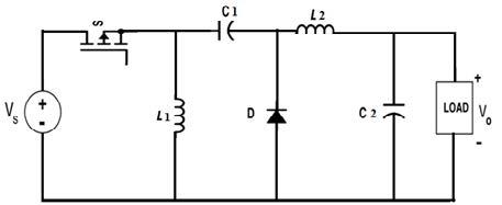
Luo converter is the highest version of boost converter and SEPIC converter. The Figure 1 shows the proposed DC-DC Luo converter. The inductance L1 and L2 stores the energy; inductor L2 maintains the output current as continuous. Luo converter input current also remain continuous due to this property converter efficiency becomes high. The capacitor C1 and C2 acts as the filters and reduce the ripples in the voltage and current. Duty cycles define the mode of the Luo converter buck or boost because it can act as Buck-boost converter with non-inverting output.
This converter achieves double frequency ripple suppression in the output voltages. In this paper multi input Luo converter has proposed. This converter increases the performance of the overall system such that with lower duty cycle it supports high output voltage gain. The fuzzy and ANN algorithm provides maximum power tracking from the input supply system and increase the converter efficiency. In grid side, reactive power has been increased due to the nonlinear loads. Due to the nonlinear characteristics of grid, current becomes non uniform, so that a power quality becomes a major issue in grid side. This power quality problem is a major concern for affecting the grid performance. In this paper PI controller achieves grid current compensation and this makes grid current and voltage are in phase including near unity power factor operation. Finally proposed system achieves high voltage stability in the grid side. The proposed scheme is a grid connected topology it does not require any battery storage system. Generally the DC-DC Luo converter achieves 90 % efficiency, the fuzzy logic based MPPT and ANN algorithm increases the efficiency to maximum.
Figure 1. Proposed high gain DC-DC Luo converter
2.1 Operation
The Distributed generator consists of two input voltage sources, the Permanent magnet Synchronous Generator which generates three phase AC voltage and uncontrolled diode bridge rectifier makes the uncontrolled rectified DC voltage with higher order ripple contents, this DC voltage is given to the Luo converter. Another DC source is PV system, due to the temperature and irradiation variation the solar output voltage has higher order ripple contents also partial shading effect arises, this variable DC voltage is fed to the Luo converter. Two different methods are available for connections it means cascaded and parallel connection. In this work parallel operation is achieved for continuous voltage supply. Luo converter has one inductor and one capacitor in series and another one in parallel. This reduces ripples from the input voltage and current. Luo converter series inductor and diode combination achieves solution for partial shading effect. The main advantage of Luo converter is its input current is continuous with good output voltage gain.
The series and parallel diode combination provide dv/dt protection in the form of snubber protection, whereas low duty cycle converter provides high output voltage from hybrid energy system. The reference voltages and currents are measured from the input section for implementing MPPT algorithm.
The reference signal and the triangular carrier signal are compared and the pulse is given to the Luo converter single switch. The MPPT algorithm achieves constant output voltage with in the form of reduced voltage ripples. This voltage is given to the single phase voltage source inverter. The single phase VSI transforms the DC voltage into AC voltage in the form of pulsated output voltage. This pulsated AC voltage is fed to the inductive filter for making it into sinusoidal output voltage, this voltage is given to the single phase grid. Due to nonlinear loads harmonics are injected in the source voltage and current. In order to avoid the harmonics, the actual voltage and current are calculated in the grid. The maximum power is taken as reference and it is compared with actual power, the PI controller based grid synchronization is achieved for reactive power compensation.
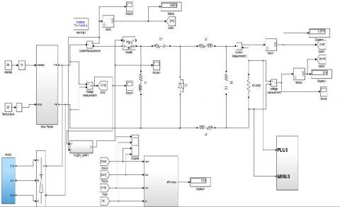
Figure 2. Proposed system circuit diagram
The proposed system model is developed as follows.
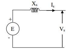
3.1 Permanent synchronous generator
The PMSG is described using equivalent circuit analysis.
VDC- Rectified DC output voltage
IDC – Rectified DC output current
Vs (rms) - Stator RMS voltage of the PMSG
Is (rms) - Stator RMS current of the PMSG
The rectified DC voltage is given as
$V D C=3 \frac{\sqrt{6}}{\pi} V s(r m s)$ (1)
$I D C=\frac{\pi}{\sqrt{6}} I s(r m s)$ (2)
Figure 3. PMSG steady state equivalent circuit
This DC voltage (1) is given to the Luo converter.
3.1.1 Solar panel
From the PV panel the PV array current is given as,
$I p v=I s c-I d$ (3)
where,
$=10^{-9} \operatorname{Isc}\left(\exp \frac{20.7}{v 0 c}(V p v+R s c . I p v)\right)$ (4)
Isc – solar short circuit current
3.1.2 Luo converter output voltage
Now the Luo converter output voltage is,
$V l u o=V o u t=\left(\frac{2-∝}{1-∝}\right) V D C$ (5)
where, $∝$-Duty cycle
The DC link current is
$I o=I l u o+I p v$ (6)
3.1.3 Voltage source inverter
The direct axis and quadrature axis voltage of the inverter is,
$V d=V D C g d$ (7)
$V q=V D C g q$ (8)
gd – Even harmonic present in the output voltage
gq – Odd harmonic present in the output current
$g d=\left(\sum_{n=1,5,9} \cos (n-1) w t-\sum_{n=3,7,11} \cos (n+1) w t\right)$ (9)
$g q=\left(\sum_{n=2,6,10} \sin (n-1) w t-\sum_{n=4,8,12} \sin (n+1) w t\right)$ (10)
Let as consider loss less power in the single phase inverter.
$I o=\frac{1}{2}(i d g d+i q g q)$ (11)
where, id, iq – Direct and quadrature axis current.
$\begin{aligned} I 0 &=I l u o+I p v \\=& \frac{(1-∝)}{∝} I D c+I p v \\ I o &=\frac{(1-∝) \pi}{\sqrt{6 ∝}} I s+I p v \end{aligned}$ (12)
In this proposed system duty cycle and the converter reference currents are varied for extracting the maximum output current at any time instants.
3.2 Operating modes
Case 1: (Hybrid system wind and solar generations)
In this case both the wind and solar are generating the power. In this operation the wind energy system provides maximum voltage (Vdc) and the solar system provides the maximum current (Ipv). So that the Luo converter duty cycle varies related with the output voltage because both input source extracts the power.
Now the MPPT reference current is given as,
Iref(new) $=\operatorname{Iref}(\text {old})+(\Delta(\operatorname{lp} v+\text {Iluo}))$ (13)
where, $(\Delta(I p v+I l u o))$ - change in current
From this reference current the fuzzy logic controller adjusts the duty cycle, so that Luo converter output voltage remains constant this voltage is fed to the inverter. Then for grid reference current it is given as,
Iref$=\sqrt{2}(V p v \cdot \operatorname{Ip} v+V d c, I d c) / V g r i d$ (14)
From this change in reference current the PI controller adjusts the pulses to the inverter so that PI controller achieves grid synchronization.
Case 2: (PMSG generating the power)
At night time the PV panel output is zero. At that time wind will supply power to the load through Luo converter.
Now the reference current is,
Iref$(n e w)=\operatorname{Iref}(o l d)+\Delta I l u o$ (15)
At this case converter extracts the maximum power from the PMSG.
Case 3: (PV generating power)
If the wind velocity is very less solar provides voltage to the system.
Now the reference current is,
$\operatorname{Iref}(n e w)=\operatorname{Iref}(o l d)+\Delta I p v$ (16)
Finally, the PV and PMSG system works together the fuzzy logic controller produces the PWM pulses to the Luo converter and the PI controller generates the reference current command from the grid, but the PI controller extracts the maximum power from the PV system. In case PMSG works alone the algorithm produces the duty cycle.
In this paper MPPT fuzzy logic and ANN algorithms are compared to extract maximum power from input system.
4.1 Fuzzy logic MPPT algorithm
The output of solar and wind energy system is non-reliable as the solar irradiation and wind speed are subjected to change. This makes it difficult to achieve efficient operation of the system. In order to get a reliable output and to help efficient operation of the system a maximum power point tracking method is applied. A MPPT algorithm constantly monitors the power output of the power generating system. If there is an increment in the power output the operating point of the MPPT system moves to a greater level this method repeated even when there is lower output by shifting the operating point in the opposite direction. A MPPT algorithm is a simple and reliable algorithm which aids in efficient operation of renewable energy based power production system. Here we have implemented a fuzzy logic MPPT algorithm.
4.1.1 Design of control rules
The fuzzy logic controller has certain rules which relate the input parameters with the output model irrespective of the system model.
This control rules are defined based on the concept that, during a transient large error require coarse control with large course input are output parameter while small error require fine control with smaller input or output variable. As per this calculation a rule table is obtained based on this rule a control is applied on the system which needs control for efficient operation.
4.1.2 Artificial neural network
Here the Artificial Neural Network (ANN) algorithm is utilized and mathematical models are provided. The simplified biological neuron system model is the neural network. It is huge parallely distributed processing system made with neural computing elements that are highly interconnected and that have the capability to learn, as a result of that it obtains knowledge and make it available for use. There are many learning mechanisms available to enable the ANN acquire knowledge.
By using simple principles Artificial neural networks (ANN) is designed. These networks are trained to identify the data as well as it comprehends the input and output relationships. The development process of ANN is subdivided into three important steps. They are
Initial stage – relevant coefficients in the ANN architecture, like weight and bias is set up carefully with the appropriate values.
Training stage – a important part of the data like observed concentration (input) and leakage source location (output) are given to the ANN.
Validation and Testing ANN models - To validate the precision of the trained ANN, new data samples are tested with the mode. Input and output mapping correlations is generated by the model. Testing of ANN is a significant stage to evaluate the execution of ANN.
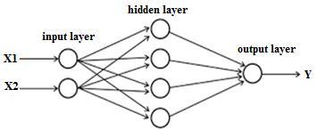
Figure 4. General structure of ANN
An Artificial Neural Network is a technique for accessing the information. It functions such as how the human brain accesses the data. ANN consists of various units of processing which are connected to work together for processing the data.
(1) Artificial Neural Network Layers
Artificial Neural network is classified into 3 layers. These layers consist of a number of interlinked nodes which constitutes an activation function.
(2) Input layer
The main function of input layer is to collect the values of input for all inspection. Generally, input nodes count in input layer is equivalent to explanatory variables count. The network patterns are presented by input layer which interact with one or more hidden layer. The layers of input nodes are submissive which means input layer do not alter the data. Input layers get a single value and duplicate the value to number of outputs. It duplicates all the values and sends to all the hidden nodes.
(3) Hidden layer
In the network specific transformations are given to the input are applied by the hidden layers. In this layer, input nodes from other hidden nodes incoming arcs are linked to each node. It is coupled with outgoing arcs to the nodes of output or to other hidden nodes. Actual processing is made by using the system of weighted ‘connection’. There may be any number of hidden layers in the ANN structure. Weights multiply the values entering into the hidden node. A single number is generated by adding the weighted inputs.
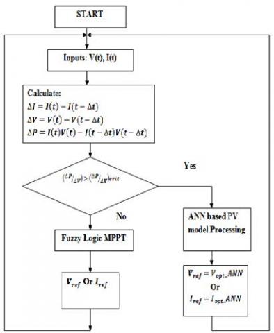
Figure 5. Proposed system flowchart
(4) Output layer
The output layers get in connection with hidden layers. Input layer or hidden layer gives connection to output layer. While classifying, generally there will be only one output node. The active nodes presenting the output integrate and alter the information to generate output values.
(5) Structure of a neural network
The neural network prediction power is increased when one or many hidden layers is added in between the layers of input and output. Hidden layers present in the ANN structure should be as small as possible. To eliminate overfitting this evaluates whether the neural network is storing all the data from the learning set.
(6) Activation functions
Processing node output is determined by the mathematical formula of activation function. All the unit takes its total input and apply activation function in to it. Activation function utilizes functions with non linearity. To control the output from reaching high value transfer function is used. Due to the non linearity Sigmoid transfer functions are utilized for network learning.
Artificial Neural Network (ANN) has been well built and implemented. A typical ANN is shown in Figure 6 has input, hidden, output layers. In MPPT, input of ANN can be photovoltaic parameters such as PV voltages, currents, data such as irradiance and temperature are any association of the above. Reference signal is the output. The reference signal may be one or several signals, whereas duty cycle signal is utilized for electronic converter to function at or closed to MPP. The input and output information are evaluated from the simulation results. The developed ANN is utilizing the voltage measurement and current measurement of PV is the ANN input, reference voltage is the output attained from MPP. By utilizing Matlab/Simulink the training data is evaluated to simulate the PV array. In all the cases with regard to particular irradiation and temperature values, the characteristic of voltage and current is recorded for ANN input. For ANN output MPP of this characteristic is recorded. To evaluate PV array voltage with maximum power the net is implemented and shown in Figure 5. The advantage of the developed algorithm is MPP tracking time is lower than fuzzy based MPPT.
The proposed work is simulated using the Matlab software. Here the device used is IGBT for reducing power losses. The FLC algorithm produces the PWM pulses to LUO converter and PI controller produces pulses to single phase inverter.
From the grid voltage, harmonics are calculated using FFT analysis. This satisfies the IEEE standard.
Table 1. Solar panel ratings
|
COMPONENTS |
SPECIFICATIONS |
|
NUMBER OF PANELS |
3 |
|
NUMBER OF CELLS IN SERIES |
36 |
|
CELL |
125 mm×31.25 mm |
|
OPEN CIRCUIT VOLTAGE |
21.4V |
|
MAXIMUM OPERATING VOLTAGE |
16.8V |
|
SHORT CIRCUIT CURRENT |
1.21A |
|
MAXIMUM OPERATING CURRENT |
1.19A |
|
OPERATING TEMPERATURE |
- 40 to +850C |
|
MAXIMUM SYSTEM VOLTAGE |
1000V DC |
Table 2. Wind power specification
|
Phase |
Speed |
AC Voltage Output |
DC Voltage Output |
Current Output |
Line to line resistance |
Mechanical Noise |
Output |
Weight |
Dimension (mm) |
|
|
r/min |
V |
V |
mA |
Ω |
dB |
W |
G |
L/W/H |
|
3 |
1500 |
15-35 |
18-38 |
≥ 2000 |
5.8 +- 0.5 |
˂ 50 |
40-56 |
395 |
80*80*26 |
Figure 6. Matlab simulink diagram
Figure 7. PMSG output voltage waveform
Table 3. Luo converter elements details
|
SL.NO |
NAME OF THE ELEMENT |
RATED VALUE |
|
1 |
L1 and L2 |
1mH / 5 amps |
|
2 |
Capacitors C1, C2 and C3 |
470uF/250 volt |
|
3 |
DIODES D1 and D2 |
FR207 -1A/1 MHz(max) |
|
4 |
MOSFET (S0) |
IRF840 - 8A/500V |
The Figure 7 shows the output voltage of the permanent magnet synchronous generator with a magnitude of 60V ac. This PMSG output is converted into DC voltage using uncontrolled diode bridge rectifier. The permanent magnet rotor creates oscillation by nature in the output voltage.
The PMSG voltage is converted into DC voltage with the help of three phase uncontrolled rectifier, the capacitive filter is used for smoothening purpose.
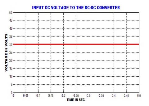
The Figure 8 shows the hybrid voltage (output of wind and solar combination) with the maximum value of 30V dc. This voltage is given to the LUO converter. Due to the variation in the input of solar panel, solar output voltage has higher order ripples.
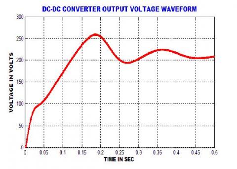
The Figure 9 shows the output voltage of the boost converter using fuzzy logic algorithm. With the input of 30V dc, the boost converter produces a voltage of 210V which stabilizes within 0.5 sec. When compared to P&O algorithm, it provides more voltage stability.
Figure 8. Input DC voltage waveform to the LUO converter
Figure 9. Luo converter output voltage using ANN algorithm
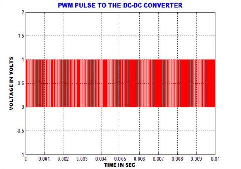
The Figure 10 shows the PWM pulse applied to the LUO converter. The MPPT based on fuzzy logic algorithm is carried out for producing the PWM pulses with switching frequency 20 KHz. The fuzzy logic algorithm is the self-tuning optimized MPPT algorithm.
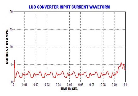
The Figure 11 shows the input inductor current waveform. Due to nonlinear loads currently have noises. The higher order harmonics in the input current is removed by the inductor L1 present in LUO converter.
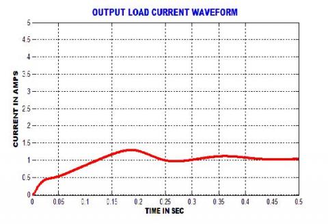
The Figure 12 shows output current waveform of LUO converter. The inductor maintains the input current at the constant with the value of 1.1A.
Figure 10. PWM pulse waveform to the LUO converter
Figure 11. Input current waveform from the LUO converter
Figure 12. Output DC current waveform of the LUO converter
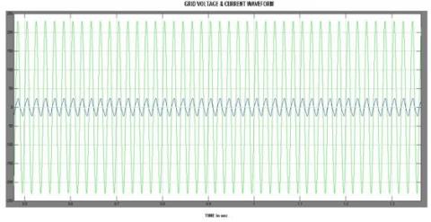
Figure 13. Grid Voltage and current waveform synchronization
The Figure 13 shows the inverter output voltage with inductive filter because voltage injected in the grid should be sinusoidal. PI controller achieves grid current compensation.
The Figure 13 shows grid voltage and current waveform, it indicates both are in phase. Thus the near unity power factor operation is achieved. This system looks likes STATCOM device.
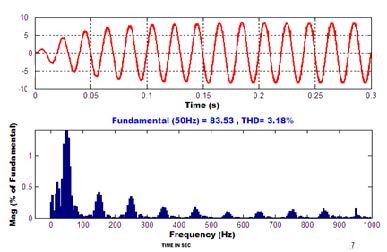
The Figure 14 shows the THD in the waveform of grid voltage which shows only 2.10 %. Thus our system satisfies IEEE harmonics standard. LUO converter and MPPT algorithm maintains constant voltage to the grid with the help of inverter. With the help of PI controller steady state operation in the grid is also achieved.
Figure 14. Voltage THD waveform
5.1 Comparison of boost converters
The proposed system is validated through fuzzy logic based MPPT algorithm, ANN and P&O algorithm. This chapter deals with comparison between proposed converters with Boost converter.
Table 4. Comparisons between proposed converters
|
S No |
Parameters |
Luo Voltage |
Efficiency |
Voltage THD |
Current THD |
|
1 |
Output Voltage (P&O) |
178 V |
91 |
2.2 |
4.2 |
|
2 |
Output Voltage (FUZZY) |
198 V |
96 |
1.9 |
4.03 |
|
3 |
Output Voltage (ANN) |
210 V |
97.8 |
1.7 |
3.18 |
Hybrid generation system based on PV and wind based LUO converter has been successfully implemented. The performance of the overall system has been analyzed using MATLAB simulation. From the results we can say the system can work both simultaneously or separately. The fuzzy logic algorithm extracts only the maximum power from the input sources, compared to other all algorithms fuzzy logic algorithm provide has less ripple content with the help of LUO converter. Here the PI controller achieves the grid current synchronization. Due to this, inverters have very less Total Harmonic Distortion. And inverter obeys the power quality issues and harmonics standard theory levels. Comparison is shown for fuzzy and ANN.
In between the LUO converter with fuzzy logic and ANN MPPT algorithm provides good performance. Finally this application is mainly useful for reactive power compensation in smart grids and power grids.
[1] Koteswararao, M., Pawanputhra, P. (2013). Control performance evaluation of solar PV cells connected to an AC grid. Indian Streams Research Journal, 3(11): 1-7.
[2] Esram, T., Chapman, P.L. (2007). Comparison of photovoltaic array maximum power point tracking techniques. IEEE trans. Energy Converters, 22(2): 439-449. https://doi.org/10.1109/tec.2006.874230
[3] Fang, D., Xu, W.Y. (2013). Input-parallel output-parallel DC-DC converter with MPPT technique for grid connection of multiple distributed generators. IEEE Conference on Industrial Electronics and Applications (ICIEA), 1: 2329-2332. https://doi.org/10.1109/iciea.2016.7603981
[4] Femia, N., Petrone, G., Spagnuolo, G., Vitelli M. (2005). Optimization of perturb and observe maximum power point tracking method. IEEE Trans. Aerospace. Electro Systems, 20(4): 963-973. https://doi.org/10.1109/tpel.2005.850975
[5] Amelian, M., Saberi, H. (2014). Small signal stability improvement of a wind turbine-based doubly fed induction generator in a micro grid environment. International Conference on Computer and Knowledge Engineering, 1: 2093-2099.
[6] Syafaruddin Karatepe, E, Hiyama, T. (2009). Artificial neural network-polar coordinated fuzzy controller based maximum power point tracking control under partially shaded conditions. IET Renew Power Gener, 3: 239-53. https://doi.org/10.1049/iet-rpg:20080065
[7] Patel, H., Agarwal, V. (2009). A Single-stage single-phase transformer-less doubly grounded grid-connected PV interface. IEEE Transactions on Energy Conversion, 24: 93-101.
[8] Pathy, S., Sridhar, R. (2013). A modified module integrated - interleaved boost converter for standalone photovoltaic (PV) application. IEEE International Conference on Renewable Energy Research and Applications (ICRERA), 1: 989-994.
[9] Reza, S., Salwah, S., Salim, B. (2014). Neuro computing Real-time frequency-based noise-robust automatic speech recognition using multi nets artificial neural networks: A multi-views multi-learners approach. Neuro Computing, 129: 199-207.
[10] Radjai, T., Rahmani, L., Mekhilef, S., Paul, J. (2014). Implementation of a modified incremental conductance MPPT algorithm with direct control based on a fuzzy duty cycle change estimator using dSPACE. Sol. Energy, 110: 325-337.
[11] Zhang, H., Cheng, S.Y. (2011). A new MPPT algorithm based on ANN in solar PV systems. Advances in Computer, Communication, Control & Automation, LNEE, 121: 77-84.
[12] Shalini, K., Barnabas Paul Glady, J. (2016). Solar powered Luo converter for wiper motor application. Indian Journal of Science and Technology, 9(43). https://doi.org/10.17485/ijst/2016/v9i43/104663
[13] Siddharthan, N., Balasubramanian, B. (2019). Performance evaluation of SEPIC, Luo and ZETA converter. International Journal of Power Electronics and Drive Systems, 10(1): 374-380. https://doi.org/10.11591/ijpeds.v10n1.pp374-380
[14] Shanthi, P., Uma, G., Keerthana, M.S. (2017). Effective power transfer scheme for a grid connected hybrid wind/photovoltaic system. IET Renewable Power Generation, 11(7): 1005-1017. https://doi.org/10.1049/iet-rpg.2016.0592
[15] Bouselham, L., Hajji, M., Hajji, B., Bouali, H. (2017). A new MPPT-based ANN for photovoltaic system under partial shading conditions. Energy Procedia, 111: 924-933. https://doi.org/10.1016/j.egypro.2017.03.255
[16] Bhatnagar, P., Nema, R.K. (2013). Maximum power point tracking control techniques: State-of-the-art in photovoltaic applications. Renewable and Sustainable Energy Reviews, 23(C): 224-241. https://doi.org/10.1016/j.rser.2013.02.011