Ali Jaafar Dakhil![]() | Mohammed A. Shuber*
| Mohammed A. Shuber*
© 2024 The authors. This article is published by IIETA and is licensed under the CC BY 4.0 license (http://creativecommons.org/licenses/by/4.0/).
OPEN ACCESS
This study investigates into the influence of opening size and steel tube thickness on the structural properties of reinforced concrete beams, particularly those with utility ducts and pipes. Four reinforced concrete beams were subjected to comprehensive testing, including a reference beam devoid of openings and three specimens featuring square openings of varying intensities. The evaluation encompassed crucial parameters such as load-deflection response, ultimate failure load, cracking load, cracking pattern, stiffness criteria, and ductility index. Employing the Digital Image Correlation (DIC) method, detailed analyses of cracking behavior were conducted. Unstrengthened beams exhibited a reduction in ultimate load capacity and stiffness, approximately 11.18% and 19.8% lower, respectively, compared to the control beam. Introduction of a steel tube significantly enhanced the performance of opening beams, manifesting in improved cracking load, cracking formation, ultimate capacity, stiffness, and ductility index, thereby promoting more ductile behavior. Strengthened beams with 2 and 3 mm-thick steel tubes demonstrated an approximate 9.27% and 28.47% increase in ultimate load compared to their unstrengthened counterparts. Beams featuring 3 mm-thick steel tubes exhibited behavior akin to the reference beam in terms of load-vertical displacement curves, albeit with a 14.12% disparity in ultimate load capacity. Despite a somewhat identical crack morphology across all tested beams, unstrengthened beams displayed higher crack width and deflection than their strengthened counterparts.
square opening, flexural performance, strengthening, steel tube, reinforced concrete, varying thickness, DIC
In practical construction, openings are often created in beams to allow for the smooth flow of essential services like telephone lines, water supply, air conditioning, power, and sewage. This involves setting up a network of ducts and pipes, usually installed below the ceiling. These beam openings serve as a cost-effective alternative to extensive dropped ceilings, particularly in tall buildings, leading to significant savings [1, 2]. As a result, it becomes possible to reduce the number of floors in buildings, while also lessening the weight of the concrete beams. This not only eases the pressure on the building's support structure under both normal and seismic conditions but also results in substantial cost reductions. In reinforced concrete (RC) beams, the web openings may adopt a number of shapes, such as rectangular, trapezoidal, circular, and numerous more. The more frequent shapes for utilization are rectangular and circle-shaped [3]. The behaviour of the beams changes as openings are incorporated. A reinforced concrete beam's capacity to bear loads is decreased and its service-load deflections are increased in the presence of an opening. The deflection was influenced similarly, as the moment of inertia decreased in the opening sections. In the early 1960s, researchers delved into the study of beams with openings, aiming to comprehend their behavior under various conditions. In a study referenced as [4], 27 reinforced concrete beams with openings of different sizes, shapes, and horizontal positions were tested. The findings revealed that the position of the openings in the flexure zone had less impact on the beam's performance compared to the shear zone. Interestingly, circular openings had the least effect on reducing the ultimate load. The areas near the openings exhibited transverse cracks and stress concentration at the corners. Another study by Hanson [5] focused on longitudinally reinforced T-beams with square and circular apertures in the web, mimicking a typical joist floor. It concluded that an opening near the center support did not weaken the beam. However, reduced beam stiffness could lead to excessive deflection under the service load and alter the distribution of internal moments and forces within the beam [6-8]. Authors in the study of Mansur [9] warned that openings in beams pose a potential risk. Numerous experimental investigations [10-13] have indicated that openings can cause premature failure of beams due to unexpected propagation of inclined cracks in the compression chord. While concrete boasts significant compressive strength, it is brittle and weak in tensile strength [14]. Consequently, the properties of opening reinforced concrete beams have to be enhanced to reach a satisfactory level of performance when used as concrete structural.
Numerous strategies have been implemented to overcome the negative performance of openings in RC beams. Fibre-reinforced polymer (FRP) laminates the strength of RC beams. Popular strategies proposed for building construction for the strengthening of structural members include [15-22]. Mansur [12] investigated the way reinforced concrete beams with web openings were designed. A total of four "T beam" specimens, including S, O, O-G, and O-FRP, were tested. All specimens have the same size. The beams 'S' and 'O' were designed without openings in order to withstand the consequences of constructing openings. The opening in the beam 'O-G' was filled with non-shrink grout. As a result, the beam "O-FRP" was reinforced with FRP plates. Latha and Kumar [23] studied the manner in which R.C. beams performed when they were given circular openings with varied percentages of openings. Six models in all were investigated, and a finite element method was used for each model by applying a two-point load. The incorporation of composite sheets or additional steel reinforcement around the opening region might enhance the numerical method's effectiveness in describing the test's influence on load deflection, cracking pattern, and the strength of the R.C. beam. S.C. Similar findings were also observed in [24, 25]. Chin et al. [25] investigation of renovation CFRP materials into R.C. beams with large hollow areas at bending zones Five R.C. beams, each 2000mm in length, with a cross section of 120×300mm one solid beam with no gaps. Two unsupported beams with 210×210mm square and immense circular openings (230mm in diameter). Due to a concentration of significant stress at the four sides of massive square openings, where cracks initially appeared, it was shown that square openings often behave as a smaller ultimate load than broad circular openings. All the previous research focused on post-planned enhancement of openings, which involves drilling holes in an existing building for a recently constructed structure. When constructing utility pipes and ducts, issues are possible.
On the other hand, internal strengthening in the case of pre-planned openings includes steel reinforcement installed at the upper and lower chords and diagonal reinforcement placed around the opening [26-28]. In recent years, there has been a lot of attention dedicated to enhancing the performance of opening RC beams with the addition of reinforcing the internal surface of the opening with different thicknesses of steel tube. Based on the reviewed literature, these researches utilizing manual techniques to measured deflection, crack pattern, strain, and crack width. These techniques are time-consuming and prone to measurement errors, which might have an influence on the procedure for testing and, in the case of loading rate dependence, the structural behaviour. Furthermore, measurements at (or near) failure of elements that have little deformation capacity are typically removed due to the danger to worker safety and equipment damage. Digital image correlation (DIC) is a very significant special instrumentation modern technology for the non-invasive measurement of surface deformations in the full field. Consequently, the DIC technique combines with the deformation theory by utilizing visual assessing to produce digital images of the specimen before and after deformation [29-32]. The images are then analysed to find the relative displacement field, presenting the strain distribution on the specimen's deformed surface. Numerous research has used technology that combines the DIC technique with micrographic imaging to perform micro-range strains [33]. Based on laboratory results, the DIC method is effective for observing and analyse nano-scale deformation.
In this study, the aim was to investigate the influence of steel tubes on the flexural behaviour of opening reinforced concrete beams. Two types of steel tubes at two different thicknesses of 2 and 3mm were used. Rectangular openings in the middle of RC beams have been used. A series of rectangular reinforced concrete beams were prepared and tested until failure. The performance of the tested beams was assessed in terms of cracking load, load-deflection response, ultimate failure load, crack morphology, stiffness, and ductility index. A comparison was also made between the experimental test results and the results obtained using DIC technology in cracking behaviour.
2.1 Materials
Table 1. Sieve analysis result of the fine aggregate
|
Sieve Size (mm) |
% Passing by Weight |
Limits of Iraqi Specification (NO. 45/1985) |
|
10 |
100 |
100 |
|
4.75 |
97.2 |
90-100 |
|
2.36 |
85.8 |
75-100 |
|
1.18 |
81.6 |
55-90 |
|
0.6 |
47.8 |
35-59 |
|
0.3 |
23 |
8-30 |
|
0.15 |
4.2 |
0-10 |
Table 2. Sieve analysis of coarse aggregate used in this study
|
Sieve Size (mm) |
Cumulative Passing % |
Limit of IQS (No. 45/1984) |
||
|
|
|
Size (5-14) |
Size (5-20) |
Size (5-40) |
|
37.5 |
100 |
- |
100 |
100 |
|
20 |
100 |
- |
95-100 |
- |
|
14 |
- |
- |
- |
95-100 |
|
10 |
47 |
100 |
30-60 |
35-70 |
|
4.75 |
0 |
90-100 |
0-10 |
- |
Table 3. Steel reinforcing characteristics used in this study
|
Property |
$\emptyset$ 10 |
|
Actual bar diameter (mm) |
10 |
|
Area (mm2) |
78.54 |
|
Yield stress (MPa) |
552.0 |
|
Ultimate strength (MPa) |
667.9 |
|
Elongation % |
14.17 |
In this study, Type I Portland cement, commonly known as (Krasta), met the requirements of the Iraqi Specification (IQS). Natural sand with a particle size of 4.75mm and a specific gravity of 2.61 was used, as specified by IQS (see Table 1). It was used in saturated surface dry conditions (S.S.D). Natural aggregate (NA) was used as coarse aggregates with a maximum size of 20mm and a specific gravity of 2.63. The sieve analysis and physical properties of this aggregate are presented in Table 2. It met the IQS No. 45/1984 requirements and was used in S.S.D conditions. Ordinary tap water was used for mixing and curing the tested specimens in this research. The steel tube with thicknesses of 2 and 3mm had a yield stress of 300 MPa for this investigation. Steel bars numbered 10 were used for longitudinal reinforcement, compression, and web reinforcement. The direct tensile strength of 3 specimens for each bar diameter is shown in Table 3.
2.2 Details of the tested RC beams
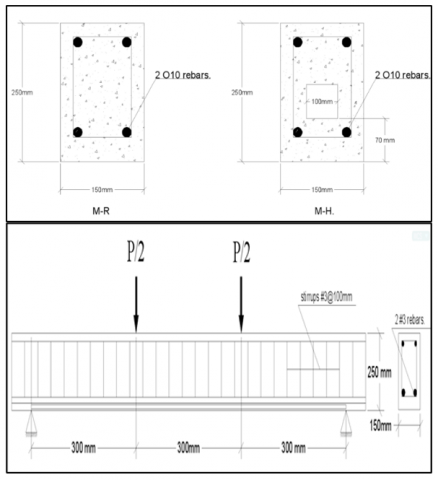
Figure 1. Tested beam specifications, (all dimensions are in mm)
Table 4. Notation of the tested beams
|
Beam Designation |
Beam Details |
|
M-R |
Flexural beam-Reference beams (without opening) |
|
M-H |
Flexural beam-Hollow beams (with opening and unstrengthen beams) |
|
M-HS2 |
Flexural beam-Hollow square opening strengthening by 2mm (strengthen by steel tube) |
|
M-HS3 |
Flexural beam-Hollow square opening strengthening by 3mm (strengthen by steel tube) |
In this study, the experimental work involved testing four rectangular reinforced concrete beams. These beams measured 150mm in width, 100mm in depth, and 900mm in length. The testing process involved subjecting the specimens to a four-point load test to assess their performance. A total of four specimens were tested to evaluate their flexural failure. One of the beams served as a reference and was made of normal concrete without any openings in the mid-span. The other beams were designed with openings in the flexural zone, including one beam without strengthening and the remaining two beams with a square opening reinforced using steel tubes. The bottom of the beams was reinforced with two 10mm diameter deformed bars, while two 10mm diameter bars were added at the top for practical reasons. Additionally, closed stirrups with a diameter of 10mm at 100mm spacing were incorporated as web reinforcement in the shear zone. The beam's design details adhered to ACI 318-19. The geometric characteristics of the tested beams are illustrated in Figure 1, and Table 4 provides the notation for each tested beam.
2.3 Concrete specimens casting and testing
Mixtures aiming for a compressive strength of 35 MPa exhibited fairly standard strength. In this experiment, we created regular concrete mixes using similar amounts of Portland cement, fine and coarse aggregates in a 1:2:4 ratio, and a water/cement ratio of 0.4. The strength of the hardened concrete was assessed based on its compressive strength after 28 days. We followed the guidelines of EN 12390-3 to measure the compressive strength of 100×100×100mm cubes. To cast the normal concrete beams, we constructed four plywood cages (moulds) using bolts for the bottom and side pieces, each with a 20mm thickness. The first step in building the simply supported beams was to oil their internal sides. After that, we installed the reinforcement in the mould before casting. For the normal concrete (NC), we used a vertical portable mixer with a 0.2m3 capacity to mix the fresh concrete. To ensure the concrete filled every gap and eliminate voids, we used an electrical vibrator after casting the concrete. Following that, the top surfaces of the moudels were modified, and the beam sample moulds were cast. Figure 2 shows the mixing and casting process for the tested specimens. In this specimen, a square opening section was used with dimensions of 100*100mm in the mould (except reference beams). For strengthening specimens, they have been propped up with square steel tubes having two thicknesses, which are 2mm and 3mm. The specimens were then stored in a covered laboratory environment to preserve them in a humid environment. As soon as the specimens achieved their required age, the formworks were removed up, and they were covered with polypropylene sheets to maintain a semi-controlled the environment (see in Figure 3).
Figure 2. Casting procedures for normal concrete (reference beams)
Figure 3. Curing of the specimens
Figure 4. Schematic drawing of the load application mechanism
Figure 5. Instruments supplied for testing (LVDT devise)
2.4 Instruments and testing machine
The tests were carried out using the machine shown in Plate at the University of Al-Structural Qadisiyah's Civil Engineering Laboratory (Figures 4 and 5). The beam was constructed in accordance to ACI 318-19. After 28 days, all beams are painted white to allow for a subsequent crack drawing. A hydraulic jack that goes downward and applies pressure to a load cell with a 2000kN capacity created the load for the testing device. The load cell, which was fixed above a stiff steel beam, was used to provide two-point loads to the tested specimen. Three supports were used to support the tested specimen: one hinge support in and roller supports at the beam's edges. A linear variable differential transformer, LVDT (Figure 5), with a maximum capacity of 50mm, was used to measure the deflection at the beam mid span (maximum flexural moment location) corresponding to the applied load. Loading has begun by applying a single point load from the testing machine to the top midway of the loading bridge. After being evenly divided into two loads, the single weight is then delivered to the concrete beam through the two steel bars supporting the bridge.
2.5 Testing procedure
After the curing period of 28 days, the beam samples were dried out in the lab before having their exteriors painted white so that the crack patterns could be observed during the test. The LVDT devices were adequately positioned out and attached at the correct places when the beam had been set up in the testing machine, and it had been horizontally adjusted at the test rig's center. The load was applied gradually up to the first crack stage (about a 5 kN increment), and then it was raised at a constant increment rate of 10 kN up to the maximum load. The test continued on until one of the cases appeared. First, a significant reduction in the overall applied load levels. Second, at the same time as the beam is being loaded, deformations and crack spreading occur in place. Concrete would eventually be crushed.
3.1 Ultimate load
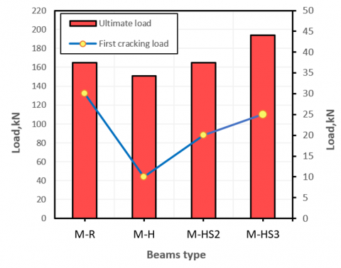
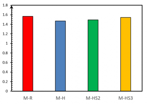
The results of the tests depicted in Figure 6 show how the opening parameters affect the overall strength of the tested beams. When the applied load reached 170 kN, the control beam-without any perforations-completely collapsed. The initial unstrengthened beams with openings (M-H) displayed variations in their ultimate load capacity based on the behavior of the openings. The failure of the beam occurred at 151 kN, showing an 11.18% decrease in strength compared to the reference beam when transverse holes were added in the flexure zone. Specimens M-HS2 and M-HS3 exhibited higher load-carrying capacities, with reported collapse loads of 165 kN and 194 kN, respectively. The change in strength was marginal compared to specimens M-R and M-H (-2.9% and +14.11%, respectively). The incorporation of openings reduced the contribution of concrete to the overall strength of the opening section in the tested beams. Conversely, the ultimate load increased when the opening was reinforced with a steel tube, particularly when the thickness of the steel tube was increased.
The measured first cracking load ranged from 10 to 30 kN for the beams under testing. The first crack load decreased by approximately 66.67% for the unstrengthened beams in comparison to the reference beam (M-R). Conversely, for the strengthened opening beams, the reduction in first cracking load was 33.33% for M-HS2 and M-HS3 beams compared to the reference beams (M-R), while it showed an improvement of about 50% compared to the unstrengthened opening beams (M-H).
Figure 6. Ultimate and first cracking load for tested beams
Figure 7. Load-deflection response for beams
Table 5. Ultimate loads of the tested beams
|
Beams Notation |
$\Delta_{\max }$ |
$P_u$ (kN) |
$\frac{\boldsymbol{p}_{u i}-\boldsymbol{p}_s}{\boldsymbol{p}_s} \%$ |
|
M-R |
10.3 |
170 |
-- |
|
M-H |
9 |
151 |
-11.18 |
|
M-HS2 |
6 |
165 |
-2.9 |
|
M-HS3 |
10 |
194 |
+14.12 |
*Ps means ultimate load for reference M-R, Pui means ultimate load for other beams, (+) means increase (%) in the above properties with respect to the reference beam
3.2 Load-mid span deflection
The experimental results of the tested beam specimens are presented in Table 5 and Figure 7. It's evident that the unstrengthened beams with openings (M-H) were less stiff than the solid beams (M-R reference beam). As for the strengthened beams, Figure 7 demonstrates how the use of a steel tube effectively improved the stiffness and load-deflection of the opening beams. The strengthened beams showed higher stiffness than the non-strengthened opening beams, especially when a 3mm thick steel tube was added. Additionally, the ultimate load changes for M-H, M-HS2M, and M-HS3 beams were -11.18%, -2.9%, and +14.12% respectively compared to M-R beams, while the respective increases for M-HS and M-HS3 beams were +9.27% and 28.47% compared to M-H beams. The test results also indicate that the use of a steel tube can significantly improve the ultimate load, with these improvements being strongly influenced by the thickness of the steel tube.
According to the test results, it is evident that incorporating a steel tube can significantly enhance the maximum flexural load of an M-HS3 beam, and these enhancements were largely influenced by the thickness of the steel tube. This improvement is primarily attributed to the use of a steel tube, which simultaneously increased the compressive resistance and ductility of this section, thereby providing the connection with additional capacity. Figure 3 revealed that while the beam specimen reinforced with a 3mm steel tube failed in flexure, its mode of failure appeared to be more ductile compared to other open beams.
3.3 Crack pattern
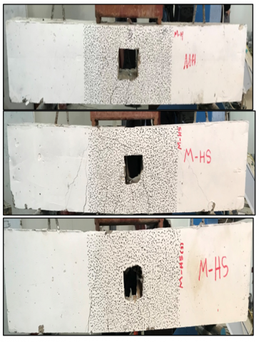
Figure 8. The cracks pattern of tested beams
The cracks that formed under the applied loads were observed along the entire length of the tested beams. It's important to note that during the crack development stage, critical areas-usually vertical ones-where the cracks first appeared, were located in the middle sections of the beams (the main area under tension). As the bending forces increased, diagonal cracks emerged and spread. The existing cracks then widened, and smaller cracks began to form. The progression of cracks in both strengthened and unstrengthened beams is depicted in Figure 8. As shown in the figure, specimens M-H exhibited closely spaced and wider cracks compared to the reinforced specimens (M-R). This suggests that the reinforcement method has altered the behavior of the hollow beams and redistributed the cracks. The figure also clearly shows that the cracks in the hollow beams passed through the opening. In contrast, for the reinforced specimens, the cracks continued along their original paths after passing around the steel tubes.
3.4 Stiffness criteria
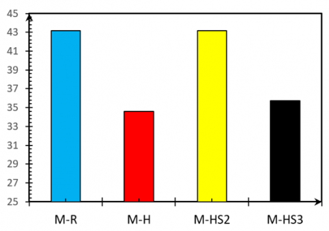
Stiffness is the quantity of force needed to deform part as one unit. The stiffness criteria were the slope of the secant drawn to each cycle in the hysterical curve at loading 0.75 times the highest load of that cycle. The stiffness of the 2mm and 3mm-thick steel tubes for the tested beams has decreased, reaching 0.03% and 17.29% compared to the reference specimen (M-R), which means an enhancement of about 25% and 3% when compared with unstrengthened opening beams. The improvement in flexural capacity and stiffness criteria, as shown in Figure 9 and Table 6. The reason for this enhancement is using strengthen opening, which has high flexural strengthen.
3.5 Ductility index
Ductility is the capacity of a structure to resist large cyclic deformations in the inelastic region without suffering an appreciable loss of strength. For designers to create structures with sufficient Ductility, they must have methods for assessing the Ductility of structural components and their connections. The ductility index, important in reinforced concrete structures, can be determined by dividing the ultimate displacement ($\triangle$u) by the yielding displacement ($\triangle$y). Although the force-deformation connection must not have a clearly defined yield point, measuring the yield deformation (displacement, rotation, or curvature) may be difficult.
The displacement ductility index has been defined as the ratio of the displacement corresponding to 85% of the maximum load on the post-peak portion of the curve to the displacement corresponding to 75% of the ultimate load (first yield displacement), according to the definition that is most commonly used. When opening plain concrete is brittle and falls down immediately when the first crack appears, its degree of ductility can be considered to be zero. Nevertheless, due to its strengthening, steel tube exhibits a distinct and superior mechanical performance in the areas of both strength and ductility. As a result of these properties, steel tube is suitable for applications requiring impact, blast, and seismic loading.
It implies that increasing thickness steel tube would enhance the section's overall strength. Table 7 and Figure 10 illustrate the ductility values for the tested specimens. It shows that tested beams decreased toughness compared with reference (M-R) by about (6.37%, 4.79%, and 1.4%) for specimens (M-H, M-HS2, and M-HS3), respectively. Whereas an enhancement of about 1.5% and 5.10% when compared with unstrengthened opening beams (M-H). Theses these enhancements in tested specimens it can be concluded that thickness of steel tube produced used so, which results in not only higher strength but also higher ductility because it is more effective in transferring the tensile force across the crack width than otherwise case.
Table 6. Stiffness criteria of tested specimen
|
Specimen Symbol |
0.75 Pmax* (kN) |
Deflection at 0.75 Pmax (mm) |
Stiffness, K (kN/mm) |
$\begin{gathered}\frac{\boldsymbol{K}_{\boldsymbol{i}}-\boldsymbol{K}_{\boldsymbol{r}}}{\boldsymbol{K}_{\boldsymbol{r}}} \\ * \mathbf{1 0 0} \%\end{gathered}$ |
|
M-R |
142.5 |
3.3 |
43.18 |
-- |
|
M-H |
112.5 |
3.25 |
34.61 |
-19.8 % |
|
M-HS2 |
120 |
2.78 |
43.165 |
-0.03 % |
|
M-HS3 |
150 |
4.2 |
35.71 |
-17.29% |
*max applied load: (i)=Stiffness of the considered specimen, (r)=Stiffness of the reference specimen
Table 7. The results of ductility index
|
Specimen Symbol |
$\Delta_y$ (mm) |
$\Delta_u$ (mm) |
Ductility Index, DI |
$\begin{gathered}\frac{D I_i-D I_r}{D I_r} * \\ 100 \% *\end{gathered}$ |
|
M-R |
4.8 |
7.52 |
1.567 |
-- |
|
M-H |
4.35 |
6.4 |
1.47 |
+58 % |
|
M-HS2 |
3.55 |
5.3 |
1.492 |
+64 % |
|
M-HS3 |
5.5 |
8.5 |
1.545 |
+80 % |
*r: Reference beams, i: Another specimen
Figure 9. Stiffness criteria for tested specimens
Figure 10. Ductility index for tested specimens
Digital image correlation (DIC) is an unconnected and enabled optical measurement technology used to determine the deformation and deflection area of the specimen surface under any load type. Particularly, it allows measurements of the studied member over the entire visible surface not just at discrete points of the limited number. In addition, DIC is able to monitor early cracks without the need to pause the test so that new cracks can be distinguished and measured; the quality of the latter is particularly useful in dynamic testing. Furthermore, DIC technique has been successfully applied to many structural problems of mechanical and civil engineering due to its many advantages, such as full field of non-contact measurement, which is simple and it continues until failure. In contrast, the use of conventional techniques such as strain gauges does not allow accurate estimation for measuring the strain. In the critical part close to failure, the strain gauges may be partially or fully destroyed. Additionally, the strain gauges measure the stain response at the fixing points only and therefore it does not provide a full field analysis of the tested members.
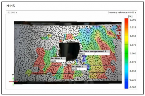
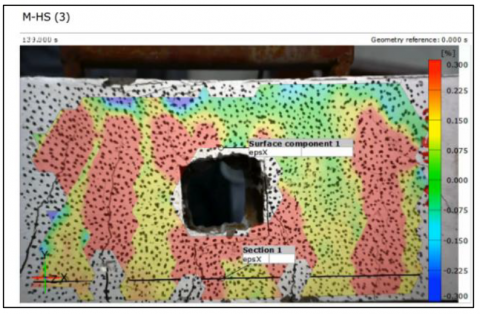
Figure 11. Failure mode for beams using DIC method
In this study, DIC can be used to investigate the cracking patterns and their development during specimens testing. The captured images are processed at different load levels compared to the reference images taken prior to loading. Figure 5 shows the crack pattern and developed crack within the load application. The cracking pattern and cracking distribution of the tested beams are all reasonably captured by utilizing the DIC approach (see in Figure 11). This technique allows for the initial deduction of any cracks and strains. As an illustration, the first crack was recorded as 10, 20, and 20 KN for M-H, M-HS2, and M-HS3, respectively. This shows that steel tube reinforcement delays the initial crack propagation more, although steel tube of 3mm thickness was more effective than steel tube of 2mm thickness. The profile also shows that the opening specimens' entrance was where the strain was concentrated. The strain concentration nevertheless did increase at a certain distance from the holes for the specimens reinforced with steel tubes.
This study presented a research instrument on flexural behavior of strengthen and unstrengthen opening reinforced concrete beams. The test results pointed out the following:
1. Opening Reinforced concrete beam with less stiffness, a smaller cracking moment, and less flexural deflection than solid beams. However, the use of steel tube significantly increased these characteristics.
2. Steel tube increased the stiffness, ultimate load, and cracking load of simply tested beams.
3. Steel tube reinforcing in opening beams increases their capacity to the same level as solid beams.
4. No bond slide occurred in the opening's surface where the steel plate met the concrete.
5. The opening steel tube of 3mm thickness exhibited the higher flexural cracking load (with an increase of about 14%) compared with all the tested beams.
6. As far as the ultimate flexural capacity is concerned, there were more advantages to be gained by changing thickness steel tube.
7. The strengthen steel tube of 3mm thickness could be recommended as it sufficiently achieved full compensation for the inferior structural performance opening in reinforced concrete beams.
8. By comparison to the reference beams, the first cracking load increased by around 67% and by 33%.
9. When steel tube reinforcement was employed, strain concentration was shifted away from the corner of the hollow section.
10. The crack morphology of all the tested beams were found to be somewhat identical, nevertheless, the unstrengthened beams tended to exhibit higher crack width and deflection than those of strengthened ones.
11. Steel tube can enhance the crack's mechanics.
12. The DIC technique used in this study could be suitable for measuring the deformation of reinforced opening beams, as it reasonably captured the load-deflection responses in flexural failure modes.
13. The DIC method is capable of detecting and identifying early crack development, whereas the traditional method is incapable of doing so until the loading reaches a certain level that has already caused specimen cracking or rupturing.
14. DIC was found to offer a significant advantage over traditional instruments, as it reasonably captured the crack morphology in reinforced concrete.
1. It might be advisable to investigate additional factors, such as variety opening location, shape opening, variety thickness of steel tube, and the type of applied load.
2. This work can further be extended by inclusion of steel fibers in self-compacting concrete beams.
3. The same experimental program may be applied to investigate reinforced concrete beams with various span/depth (a/d) ratios.
4. Same adopted experimental programs can be used to examine the influences of shear behavior on the performance of reinforced concrete members.
[1] Darwin, D. (2000). Design of composite beams with web openings. Progress in Structural Engineering and Materials, 2(2): 157-163. https://doi.org/10.1002/1528-2716(200004/06)2:2<157::AID-PSE23>3.0.CO;2-A
[2] Lawson, R.M. (1987). Design for openings in the webs of composite beams. CIRIA Special Publication and SCI Publication, Steel Construction Institute.
[3] Prentzas, E.G. (1968). Behaviour and reinforcement of concrete beams with large rectangular apertures. University of Sheffield, Civil & Structural Engineering.
[4] Al-Sheikh, S.A. (2014). Flexural behavior of RC beams with opening. Concrete Research Letters, 5(2): 812-824.
[5] Hanson, J.M. (1969). Square openings in webs of continuous joists. Portland Cement Assoc R&D Lab Bull.
[6] Allam, S.M. (2005). Strengthening of RC beams with large openings in the shear zone. Alexandria Engineering Journal, 44(1): 59-78.
[7] Amiri, S., Masoudnia, R., Pabarja, A.A. (2011). The study of the effects of web openings on the concrete beams. Australian Journal of Basic and Applied Sciences, 5(7): 547-556.
[8] Amiri, J.V., Alibygie, M.H. (2004). Effect of small circular opening on the shear and flexural behavior and ultimate strength of reinforced concrete beams using normal and high strength concrete. In Proceedings of the 13th World Conference on Earthquake Engineering.
[9] Mansur, M.A. (1998). Effect of openings on the behaviour and strength of R/C beams in shear. Cement and Concrete Composites, 20(6): 477-486. https://doi.org/10.1016/S0958-9465(98)00030-4
[10] Siao, W.B., Yap, S.F. (1990). Ultimate behavior of unstrengthen large openings made in existing concrete beams. Journal of the Institution of Engineers, 30(3): 51-57.
[11] Suresh, J., Prabhavathy, R.A. (2014). Behaviour of steel fibre reinforced concrete beams with duct openings strengthened by steel plates. International Journal of Advanced Information Science and Technology (IJAIST), 3(8): 53-61. https://doi.org/10.15693/ijaist/2014.v3i8.53-61
[12] Mansur, M.A. (2006). Design of reinforced concrete beams with web openings. In Proceedings of the 6th Asia-Pacific Structural Engineering and Construction Conference (ASPEC), 5-6: 104-120.
[13] Osman, B.H., Wu, E., Ji, B., S Abdelgader, A.M. (2016). A state of the art review on reinforced concrete beams with openings retrofitted with FRP. International Journal of Advanced Structural Engineering, 8: 253-267. https://doi.org/10.1007/s40091-016-0128-7
[14] Al-Rekabi, A.H., Al-Marmadi, S.M., Dhaheer, M.S., Al-Ramahee, M. (2023). Experimental investigation on sustainable fiber reinforced self-compacting concrete made with treated recycled aggregate. In AIP Conference Proceedings, AIP Publishing, 2775: 020032. https://doi.org/10.1063/5.0140655
[15] Al-Salloum, Y.A. (2007). Influence of edge sharpness on the strength of square concrete columns confined with FRP composite laminates. Composites Part B: Engineering, 38(5-6): 640-650. https://doi.org/10.1016/j.compositesb.2006.06.019
[16] Alsayed, S.H., Almusallam, T.H., Al-Salloum, Y.A., Siddiqui, N.A. (2010). Seismic rehabilitation of corner RC beam-column joints using CFRP composites. Journal of Composites for Construction, 14(6): 681-692. https://doi.org/10.1061/(ASCE)CC.1943-5614.0000124
[17] Al-Salloum, Y.A., Siddiqui, N.A., Elsanadedy, H.M., Abadel, A.A., Aqel, M.A. (2011). Textile-reinforced mortar versus FRP as strengthening material for seismically deficient RC beam-column joints. Journal of Composites for Construction, 15(6): 920-933. https://doi.org/10.1061/(ASCE)CC.1943-5614.0000222
[18] Elsanadedy, H.M., Al-Salloum, Y.A., Abbas, H., Alsayed, S.H. (2012). Prediction of strength parameters of FRP-confined concrete. Composites Part B: Engineering, 43(2): 228-239. https://doi.org/10.1016/j.compositesb.2011.08.043
[19] Elsanadedy, H.M., Al-Salloum, Y.A., Alsayed, S.H., Iqbal, R.A. (2012). Experimental and numerical investigation of size effects in FRP-wrapped concrete columns. Construction and Building Materials, 29: 56-72. https://doi.org/10.1016/j.conbuildmat.2011.10.025
[20] Alsayed, S.H., Almusallam, T.H., Ibrahim, S.M., Al-Hazmi, N.M., Al-Salloum, Y.A., Abbas, H. (2014). Experimental and numerical investigation for compression response of CFRP strengthened shape modified wall-like RC column. Construction and Building Materials, 63: 72-80. https://doi.org/10.1016/j.conbuildmat.2014.04.047
[21] Elsanadedy, H.M., Almusallam, T.H., Alsayed, S.H., Al-salloum, Y.A. (2015). Experimental and FE study on RC one-way slabs upgraded with FRP composites. KSCE Journal of Civil Engineering, 19: 1024-1040. https://doi.org/10.1007/s12205-013-0689-y
[22] Shehab, H.K., Eisa, A.S., El-Awady, K.A. (2017). Strengthening of cutouts in existing one-way spanning RC flat slabs using CFRP sheets. International Journal of Concrete Structures and Materials, 11: 327-341. https://doi.org/10.1007/s40069-017-0186-7
[23] Latha, M.S., Kumar, B.N. (2017). Behavior of reinforced concrete beam with opening. International Journal of Civil Engineering and Technology (IJCIET), 8(7): 581-593.
[24] Aykac, B., Kalkan, I., Aykac, S., Egriboz, Y.E. (2013). Flexural behavior of RC beams with regular square or circular web openings. Engineering Structures, 56: 2165-2174. https://doi.org/10.1016/j.engstruct.2013.08.043
[25] Chin, S.C., Shafiq, N., Nuruddin, M.F. (2011). Strengthening of RC beams containing large opening at flexure with CFRP Laminates. International Journal of Civil and Environmental Engineering, 5(12): 743-749. https://doi.org/10.5281/zenodo.1086279
[26] Mansur, M.A., Tan, K.H., Lee, S.L. (1985). Design method for reinforced concrete beams with large openings. In Journal Proceedings, 82(4): 517-524. https://doi.org/10.14359/10364
[27] Tan, K.H., Mansur, M.A., Wei, W. (2001). Design of reinforced concrete beams with circular openings. Structural Journal, 98(3): 407-415. https://doi.org/10.14359/10229
[28] Yang, K.H., Ashour, A.F. (2007). Inclined reinforcement around web opening in concrete beams. Proceedings of the Institution of Civil Engineers-Structures and Buildings, 160(3): 173-182. https://doi.org/10.1680/stbu.2007.160.3.173
[29] Sutton, M.A., Orteu, J.J., Schreier, H. (2009). Image correlation for shape, motion and deformation measurements: basic concepts, theory and applications. Springer Science & Business Media.
[30] Destrebecq, J.F., Toussaint, E., Ferrier, E. (2011). Analysis of cracks and deformations in a full scale reinforced concrete beam using a digital image correlation technique. Experimental Mechanics, 51: 879-890. https://doi.org/10.1007/s11340-010-9384-9
[31] Gencturk, B., Hossain, K., Kapadia, A., Labib, E., Mo, Y.L. (2014). Use of digital image correlation technique in full-scale testing of prestressed concrete structures. Measurement, 47: 505-515. https://doi.org/10.1016/j.measurement.2013.09.018
[32] Shih, M.H., Sung, W.P. (2013). Application of digital image correlation method for analysing crack variation of reinforced concrete beams. Sadhana, 38: 723-741. https://doi.org/10.1007/s12046-013-0141-5
[33] Schreier, H., Orteu, J.J., Sutton, M.A. (2009). Image correlation for shape, motion and deformation measurements: basic concepts, theory and applications. Springer-Verlag US. https://doi.org/10.1007/978-0-387-78747-3