Mohammed Salah Dimia*![]() | Mohamed Baghdadi
| Mohamed Baghdadi![]() | Ahmed Rafik Belakhdar
| Ahmed Rafik Belakhdar![]() | Rachid Rabehi
| Rachid Rabehi![]() | Nail Alaoui
| Nail Alaoui![]()
© 2024 The authors. This article is published by IIETA and is licensed under the CC BY 4.0 license (http://creativecommons.org/licenses/by/4.0/).
OPEN ACCESS
After a fire exposure, reinforced concrete (RC) structures typically retain their integrity, yet they incur significant damage due to material degradation and thermal expansion. The restoration of fire-damaged RC structures is a complex structural engineering challenge. This study presents a numerical investigation on the post-fire behavior of RC beams, subjected to parametric fire for different durations (15, 30, 60, and 90 minutes) and their retrofit method. Initially, the impact of high-temperature conditions on the residual load-bearing capacity is assessed, with a focus on beam length and support conditions as key geometric variables. Repair methods aimed at improving the post-fire performance of damaged beams are then evaluated. These methods include the use of additional reinforcement and the implementation of steel jacketing, complemented by concrete of varying compressive strengths (25, 30, 35, and 40 MPa). Eurocode models for both concrete and steel materials are used in the simulations using SAFIR software. Results indicate a decrease in load-carrying capacity with prolonged fire exposure, with capacity reductions reaching 85% for beams subjected to 90-minute fire scenarios. Application of steel jacketing markedly enhances both bending and shear resistance of the compromised beams, with the ability to restore the load-bearing capacity of one-hour fire-exposed beams by up to 112%. The correlation between repair effectiveness and the inherent resistance of the RC beams is also elucidated. Furthermore, an analytical expression is proposed for estimating the post-fire load-bearing capacity of reinforced beams, offering a practical and accurate tool for engineering assessments.
fire exposure, damaged beam, material deterioration, post-fire strengthening, numerical simulation
1.1 Backgrounds
Reinforced concrete constructions lose strength when exposed to fire; this loss can be continued even when the fire temperature comes back to ambient temperature for more time. Concrete and steel mechanical characteristics degrade, causing this decline. Thermal expansion leads concrete components to fracture and lose structural integrity. The strength and stiffness of the structural elements decrease as the temperature rises, making them less load bearing. When exposed to high temperatures, the steel reinforcement in concrete loses its strength and flexibility. This makes structural elements much less able to support weight because the mechanical properties of both the concrete and the steel reinforcement are degraded [1-4]. Elevated temperatures reduce the bond capacity between concrete and steel. This significantly affects reinforced concrete (RC) member moment capacity and stiffness. A reduction in bond strength by up to 60% occurs when the interface temperatures exceed 500℃. This loss of bond strength results in weak load carrying capacity under load service conditions [5]. Fire resistance in structures is the period under a conventional fire duration when some predefined conditions and limiting behavior occur. According to performance-based design, the limiting behavior in fire conditions is either structural collapse or loss of integrity, both of which can promote fire spread. However, it is commonly known as a deflection limit. The most recent design regulations, EN 1994-1-2 [6] and EN 1992-1-2 [7], require designers to take into account non-uniform heating due to partial security, which may be inherent to the frame system or specially applied, the degree of loading at the fire limit state, and partial security variables that are less than those used for ultimate limit states due to resiliency. The University of Sheffield has developed a three-node beam-column element over the course of the last several years. This feature was developed specifically for use in the 3D modeling of steel, composite, and reinforced concrete frames exposed to fire [8, 9]. The investment in post-fire damaged beams has been stimulated by knowledge gaps in the performance of fire-damaged beams, particularly under natural fire conditions.
1.2 Investigation of the post-fire performance of beams
Fire-induced concrete degradation and thermal flux variations can affect the post-fire performance of reinforced concrete structural elements. Studies on RC beams have focused on their lower load-bearing capability after fire exposure. The temperature of the steel rebar had an effect on the flexural capacity of RC beams [10, 11], and evaluation of post-fire conditions [12, 13] revealed that the residual shear capacity of beams decreased as the shear-to-span ratio increased.
According to Akca and Özyurt [12], the effect of water re-curing on the restoration of rigidity in reinforced concrete (RC) beams is greater than its effect on the recovery of strength. In their study, they mentioned that after 28 days of re-curing in water, the residual rigidity of RC beams subjected to a 2-hour ISO fire [14] increased by 16%. According to Agrawal and Kodur [15], the residual flexural strength may still meet the design limit at room temperature due to the increased capacity of the beam after fire exposure. This suggests that even after fire damage, the timbers may retain sufficient strength to meet design requirements under normal conditions. Thongchom et al. [16] found in a study that a steady load applied to the structure increased a temperature-dependent creep deflection, especially when the rebar reached 500°C. Continuous loading increased the creep tendency of the structure during high temperature exposure, resulting in increasing deflection over time. Yang et al. [17] demonstrated that decreasing load ratios and shear span to effective depth ratios increased fire resistance while increasing longitudinal reinforcement and stirrup ratios prevented cracking and reduced shear failure fragility. The research conducted by Yan's team [18-20] focused on the investigation of the response of pre-stressed ultra-high performance concrete (UHPC) beams subjected to ISO fire. They also developed a novel two-stage hot air curing method to mitigate spalling. Their findings indicated that this curing method not only enhanced the short-term strength of the UHPC beams but also effectively prevented severe spalling. It was also observed that pre-stressed UHPC beams with adhesives had better fire performance than those without adhesives. The review of the existing literature underscores the importance of further research on the fire behavior of beams to gain a deeper understanding of the strength performance after fire exposure. In addition, the investigation of the effectiveness of strengthening methods is an important issue to save the serviceability of the beams.
1.3 Effectiveness of the repair technique for fire-damaged beams
Post-fire beams can be mechanically repaired by applying materials to their bottoms or sides. Adjustments aim to restore beam’s flexural capacity and shear resistance. Studies show that adding more carbon fiber-reinforced polymer (CFRP) layers to a post-fire-reinforced concrete beam does not boost its mechanical performance. In fact, it has been observed that the failure mode of the repaired beams can vary from ductile failure to brittle failure when excessive layers of CFRP sheets are utilized [21, 22].
In the study conducted by Irshidat and Al-Saleh [23], it was recommended to incorporate carbon nanotubes as a means to enhance adhesive bonding. This approach was designed to address concerns related to the delamination of fiber-reinforced polymer (FRP) sheets used in the repair of reinforced concrete (RC) elements. The findings of the experiments demonstrated that the use of carbon nanotube (CNT)-modified epoxy resin had a significant impact. It pushed back the start of the debonding process and slowed it down in reinforced concrete (RC) beams that had been rebuilt with carbon-fiber-reinforced polymer (CFRP) sheets that were close to the surface. Additionally, the studies [24-27] mentioned that when compared to beams repaired with cement-based adhesive, beams fixed using epoxy adhesive showed a greater load-bearing capability. These studies found that increasing plate thickness and reducing fastener spacing resulted in improvements in post-fire RC beams repaired using the Bolted Steel Plate (BSP) method. Experimental studies have been conducted by Hassan et al. [28] on the effect of high temperatures on different types of concrete beams, these beams were retrofitted with different confinement techniques where steel plates in the form of strips were welded with threaded bars. For beam capacity recovery less than 10%, the outer orientation of the top angles is allowed. Welded plates outperformed bolts in this test. Belkhader et al. [29] looked at how well different strengthening methods, such as reinforced concrete jackets and composite jackets, can improve the behavior of RC columns after a fire, taking into account the additional loss of concrete resistance during cooling. Different values of compressive strength were considered. The results indicated that the load capacity of damaged columns could be restored by up to 182% using a composite jacket with steel plates.
This study focused on the retrofitting of RC beams with various steel jacketing techniques. Three-point pressures were applied to unheated and modified beams to determine their flexural capacity. Three different techniques for steel casing were examined. The study aimed to examine the overall behavior of the strengthened beams by varying the techniques and sizes of the steel angels. Another approach was to attach steel plates to the tensioned part of the beam to improve the performance of the beams. Steel plates and threaded bars were used to control the shear position. The inclusion or exclusion of steel angels was determined based on the required conditions and economic considerations, taking into account the recommendations of the study. Through these investigations, the study sought to evaluate the effectiveness of different steel jacketing techniques in retrofitting concrete beams. The objective of improving the overall performance, stiffness and load-bearing capacity of the beams served as the basis for the selection of specific techniques and dimensions, taking into account their feasibility and cost-effectiveness in relation to the environment.
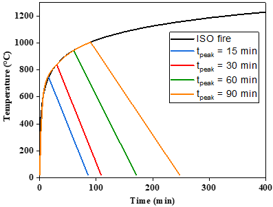
The proposed research work utilizes the computer software SAFIR [30] as the analysis tool to investigate the behavior of both unfired and fire-damaged reinforced concrete (RC) beams. The study aims to evaluate the performance of the beams before and after the application of concrete jacketing layers. The SAFIR software [30] provides a platform for conducting comprehensive analyses and simulations, allowing for a detailed examination of the structural behavior and the effects of jacketing on the fire-damaged RC beams. The main parameters are the compressive strength of the concrete (Fc'), the thickness of the concrete casing (c), and the span of the beam (L). The selected parameter values are based on practical design considerations for typical RC structures. The compressive strength of concrete considered is 25 MPa, while those of steel are specified as 415 MPa in terms of yield strength. For the concrete, the Eurocode model is adopted, Table 1, which is implemented in the SAFIR code. For steel, EN 10113-1 establishes the technical delivery criteria for hot-rolled soft weldable structural steel products with nuances S420 and S460. Welding building projects, especially those with high loads and stresses, require this steel. The safety and reliability of building materials and components depend on these requirements. The concrete jacketing is usually stronger than the original beam concrete. The study assumes the same mechanical characteristics for the concrete core and connected sheathing. The jacket thickness is 5 mm, the unwrapped beam width is 200 mm, and the span is taken 3m, 4m, and 5m. The main rebar in the concrete core is set to 2Ф18 and 2Ф20. Jacket quantity reinforcing is determined on the basis of a maximum practical spacing of 10 mm of bars laid in a single layer to resist bending loads in accordance with CSA A23.3-14 [31]. The first step was to evaluate the behavior of the RC beams after exposure to fire. The study examined the effects of various high temperature conditions (15, 30, 60, and 90 min) following by cooling phase, the Figure 1 shows the temperature-times curves used. It fully reflects the evolution of a fire at room temperature. Equation 1 is used to determine the quantity of fire exposure.
$\mathrm{T}=345 \times[\log (1+8 * \mathrm{t})]+20$ (1)
where, t the duration of exposure to fire is measured in minutes.
The structural analysis was performed by taking into account how the fire and temperature changes can affect the beam's material properties in order to evaluate how much load it can still hold after being exposed to fire. The beam is 4 meters long and has a cross section of 0.2 by 0.4 meters.
$\mathrm{H}=\lambda \times A$ contact $\times \frac{\Delta T}{L}$ (2)
where, ∆T: The temperature difference between two surfaces in contact with each other over a specific contact area is represented as (A) contact, λ: The coefficient of thermal conductivity W/ m ºC.
Figure 1. Standard and parametric temperature-time curves
The second stage consisted of evaluating the effectiveness of repair with various steel jackets by adding reinforcement and incorporating composite jackets. The techniques involved using jackets to concrete and two angels positioned at the corners of the beam. The dimensions of the corner angels were 2 L 40 × 40 × 4. Welded angels or tie rods were employed to encase the beam from three sides, attaching steel vertical jackets to concrete beams and repairing steel horizontal jackets to concrete beams.
The curve comes to an end when the applicable standard specifies the maximum amount of combustion. As depicted in Figure 1, the cooling phase begins at varying predefined maximal fire temperatures, as the dashed lines indicate. In principle, as fire duration increases, load capacity decreases. The following describes RC beams behavior repaired with composite jacketing:
- Repairing Steel Corner Jackets to concrete Beams BRSC-J
- Repairing Steel Vertical Jackets to concrete Beams BRS(V)-J
- Repairing Steel Horizontal Jackets to concrete Beams BRS(H)-J
Table 1. Relationships between stress and strain, Eurocode 2
|
Strain-Range |
Stress σ (θ) |
|
ɛc,θ≤ɛc1,θ |
$\sigma_{c, \theta}=\frac{3 \cdot \varepsilon_{c, \theta} \cdot f_{c, \theta}}{\varepsilon_{c 1, \theta}\left[2+\left(\frac{\varepsilon_{c, \theta}}{\varepsilon_{c 1, \theta}}\right)^3\right]}$ |
|
ɛc1,θ≤ɛc,θ≤ɛcu1,θ |
For numerical purposes, a descending branch should be utilized. Both linear and non-linear models are suitable. |
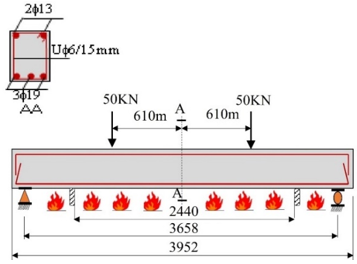
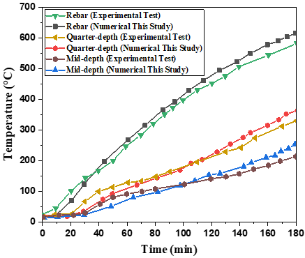
The accuracy of the current model in predicting the flexural behavior of retrofitted RC beams is confirmed by validation against experimental results obtained by Dwaikat and Kodur [32] and the numerical model developed in SAFIR. During fire exposure, no spalling of the beams was observed. Figure 2 depicts the geometry and reinforcement configuration of the beam, as well as the loading and boundary conditions. Figure 3 depicts the predicted and measured temperatures in the concrete and reinforcement rebar of a beam. The reinforcing bars used are 3Ф19 at the top and 2Ф13 at the bottom of the cross-section. The beam was subjected to a standard fire (ASTM E-119-08a, 2008) after being loaded at two constant load points. Three sides, the bottom and side surfaces of the beam, were exposed to fire within the region between the compartment walls; the upper surface of the beam was not exposed.
Figure 2. Beam tested to validate finite element model
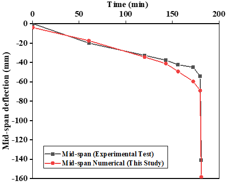
Experimental results and the SAFIR model yield consistent temperatures. The calculated and measured temperatures are very close, demonstrating the accuracy and reliability of the numerical modeling methods. According to the data presented, there are discrepancies between predicted and measured temperatures during the first 130 minutes of fire exposure.. The numerical models have a tendency to predict lower temperatures than those observed during this period. Therefore, the degradation of mechanical properties is expected to occur at a delayed rate, and the mid-span deflections of the beam are expected to be smaller than what is actually measured. The discrepancy in temperature predictions between numerical models and measurements can lead to variations in the estimation of mechanical behavior and deflection response during fire. As shown in Figure 4, the initial deflection of the beam prior to exposure to fire is selected as the initial condition for the deflection during the fire. After 140 minutes of fire exposure, the SAFIR model and the experimental test show a difference in deflection and stiffness, the numerical predicts a quicker dropStiffness loss and failure were experimentally determined at 180 minutes of fire exposure. The Safir model prediction of failure is shown to be in good agreement with experimental results. This validation highlights the need for experimental testing to understand the fire response of beams and to guide fire resistant design.
Figure 3. Measured and predicted temperatures from experimental and SAFIR program
Figure 4. Measured and predicted mid-span deflection using experimental and SAFIR program
4.1 Effect of beam span
The results for the load bearing-capacity of beams considering different spans and different fires with heating phases of period duration tpeak = 15, 30, 60 and 90 minutes are summarized in Table 2. It is important to note that the cross-sectional area (0.2 × 0.4) m2 is assumed constant. The findings led to the conclusion that long span beams exhibited lower load-bearing capacity than short beams when exposed to fire.
Table 2. Results of exposed RC beam for different spans
|
Beam Length (m) |
N20°C (kN) |
tpeak=15min |
tpeak=30min |
tpeak=60min |
tpeak=90min |
|
Ncollapse (KN) |
|||||
|
3 |
143 |
136 |
112 |
53 |
21 |
|
4 |
105 |
100 |
83 |
40 |
14 |
|
5 |
84 |
78 |
68 |
32 |
11 |
For a beam length of 3 meters, the load capacities are 136, 112, and 53 kN at maximum exposure times of 15 minutes, 30 minutes and 60 minutes respectively. The corresponding load capacity at tpeak of 90 min is 21 kN. Similarly, For a beam length of 5 meters, the load capacities are 78, 68, and 32 kN at peak durations of 15, 30 and 60 minutes respectively, while the load capacity of is 11 kN at tpeak= 90min.
4.2 Effect of fire duration
Table 3 displays data related to fire duration and its effects on load carrying capacity, deflection (Δ), and the reduction in load capacity due to fire. The reference beam has an ultimate load-carrying capacity (Pu) of 143 kN and a deflection of 12.9 mm. As the fire duration increases, the load-carrying capacity decreases, with reductions of 4.90% at 15 minutes, 21.68% at 30 minutes, 62.94% at 60 minutes and 85.31% at 90 minutes. The deflection also increases with longer fire durations, reaching 55.24 mm at 15 minutes, 64.92 mm at 30 minutes, 99.94 mm at 60 minutes, and 100.06 mm at 90 minutes.
Table 3. Results of a beam of 3m for various fire durations
|
Fire Duration (min) |
Load Carrying Capacity Pu (KN) |
Mid-Span Deflection Δ (mm) |
Reduction in Load Capacity due to Fire (%) |
|
Ref. beam |
143 |
12.90 |
- |
|
15 |
136 |
55.24 |
4.90 |
|
30 |
112 |
64.92 |
21.68 |
|
60 |
53 |
99.94 |
62.94 |
|
90 |
21 |
100.06 |
85.31 |
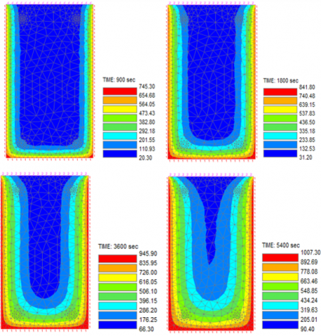
The predicted temperature profiles of typical beam sections after 15, 30, 60, and 90 minutes of fire exposure from three sides are shown in Figure 5. As the duration of exposure increases, the temperature within the beam rises towards the center, as shown in the graph. Figure 5 also demonstrates that the temperature within the beam's cross-section varies with depth. This difference can be attributed to the limited thermal conductivity of concrete.
The temperature changes were quantified via thermal analysis. The thermal response and fire performance will be assessed using the expected peak temperatures.
Figure 5. Predicted temperatures at 15, 30, 60 and 90 minutes of fire exposure
4.3 Temperature evolution
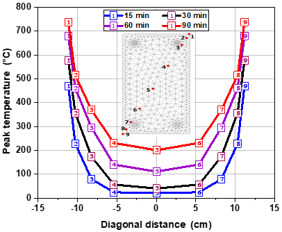
Thermal behavior was performed using finite element analysis, with peak temperatures calculated at positions 1 through 9. Figure 6 illustrates the distribution of the maximum temperatures experienced in exposed sections during fires with heating phase of 15, 30, 60, and 90 minutes. Figure 6 provides valuable insight into the thermal response and temperature profiles across the exposed sections, allowing us to understand how temperatures within these sections change over time.
Figure 6. Maximum temperature profile at diagonal cross-section
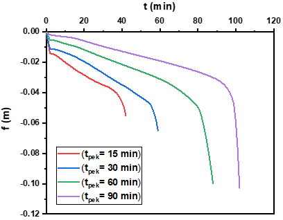
Figure 7 illustrates the relationship between the mid-span vertical displacement and the heating-up periods. The diagram depicts how the vertical displacement of the beam varies as the heating durations increase. The time of occurrence of the vertical displacement inflection point in the beam is closely related to the fire condition and the applied vertical constant load. The inflection point refers to the moment when the displacement changes its direction from increasing to falling.
Figure 7. Relationship between the vertical displacement and heating time
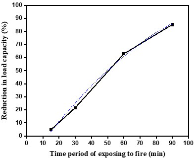
The reduction in load-carrying capacity of the beam over time after exposure to a fire event is illustrated in Figure 8. The curve portrays how the remaining load-carrying capacity decreases as time elapses, with the x-axis denoting time and the y-axis depicting the capacity as a percentage of its original value. Eq. (3) is used to quantitatively calculate the reduction in load carrying capacity at a given time, based on the principles outlined in Eq. (3). Eq. (4) is a non-linear mathematical relationship that gives this reduction in capacity. These equations provide insight into modeling and understanding the effects of high temperatures and fire damage on structural elements, helping engineers assess the structural integrity and safety of fire-damaged beams over time.
$P(\%)=\frac{P_U\left(T=20^{\circ} \mathrm{C}\right)-P_U\left(T^{\circ} \mathrm{C}\right)}{P_U\left(T=20^{\circ} \mathrm{C}\right)} \times 100$ (3)
where, $P(\%)$ Reduction in load capacity, $P_U\left(T=20^{\circ} \mathrm{C}\right)$ Load carrying capacity in $T=20^{\circ} \mathrm{C}$ and $P_U\left(T^{\circ} \mathrm{C}\right)$ Load carrying capacity in different temperature.
$P(\%)=-0.0059 t^2+1.7191 t-21.328$ (4)
where, t time of exposure to fire in minutes.
The curve in Figure 8 shows that beam load capacity declines with fire duration. Compared to the reference model, a beam subjected to a 15, 30, 60, or 90-minute fire load reduces load capacity by 4.90%, 21.68%, 62.94%, and 85.31%, respectively. It is well noted that fire significantly reduces load capacity. The structural integrity and safety of fire-damaged beams can account for these load capacity limitations.
Figure 8. Reduction in load capacity due to fire
4.4 Effect of support conditions
4.4.1 Simply beam supported (supported by pin-roller)
At the left support (pin), the beam is constrained both axially and vertically. However, at the right support (roller), the beam is free to move axially, allowing it to expand in this direction. Table 4 summarizes the results of the calculated bending moments and shear forces for the reference beam and the beam subjected to a fire of tpeak = 60 minutes.
4.4.2 Fixed–fixed beam
With fixed supports at both extremities, the entire beam is axially, vertically, and rotationally restrained, and a negative bending moment is induced at the supports. The results in Table 4 presents bending moments and shear forces for reference and heated beam. For the reference beam, the simply supported beam has a significantly higher bending moment (75.8 kN.m) compared to the fixed beam (13.92 kN.m). However, the shear force in the simply supported beam is higher (60 kN) than the fixed beam (10.56 kN. After 60 minutes of fire exposure, both beams experienced reduced bending moments and shear forces. The bending moment decreases to 33.40 kN.m in the simply supported beam and 6.68 kN.m in the fixed beam. Similarly, the shear force reduces to 25.45 kN in the simply supported beam and 5.40 kN in the fixed-fixed beam. The results suggests that the fixed beam exhibits better resistance to both bending and shear forces under fire conditions compared to the simply supported beam. These findings highlight the importance of choosing the appropriate beam type based on the specific structural requirements and fire safety considerations.
Table 4. Bending moment and shear forces in beams after 60 minutes of fire
|
Fire Duration (min) |
|
Simply Beam Supported |
Fixed–Fixed Beam |
|
Reference beam |
Bending moment (kN.m) |
75.8 |
13.92 |
|
Shear force (kN) |
60 |
10.56 |
|
|
60 min |
Bending moment (kN.m) |
33.40 |
6.68 |
|
Shear force (kN) |
25.45 |
5.40 |
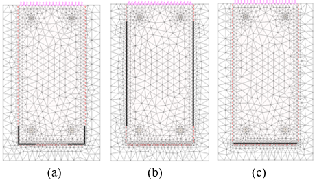
Repairing and strengthening beams after a fire with a composite steel jacket is a rehabilitation technique that combines the use of composite materials to restore the damaged beams' structural integrity. This method is particularly effective when it is necessary to provide both fire resistance and an increased load bearing capacity at the same time. The concrete material provides fire resistance and the steel adds significant load-carrying capacity. Figure 9 illustrates a post-fire technique used to strengthen beams by applying steel plates bonded to a 5 cm concrete jacket. This method is used to enhance the load-bearing capacity and structural integrity of existing damaged beams. This post-fire strengthening technique is commonly employed in structural engineering to rehabilitate and restore the structural performance of fire-damaged beams, ensuring that they meet safety and load-bearing requirements. The specific dimensions, materials, and bonding processes may vary depending on the engineering design and the extent of fire damage.
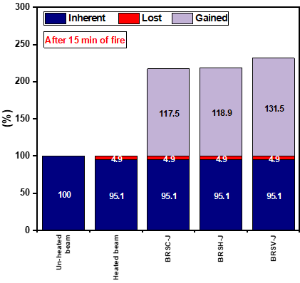
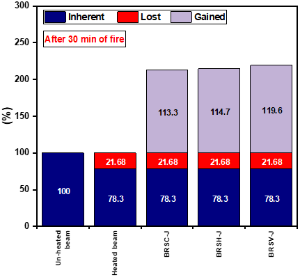
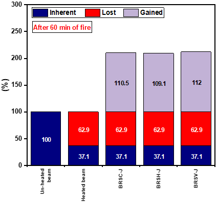
Table 5 provides information on the duration of a fire in minutes and its effect on the load-bearing capacity (Pu) using finite element analysis (FEA). The results showed that fire intensity can reduce and significantly affect the load carrying capacity of beams and also demonstrated the efficiency of different retrofit techniques used: (BRSC-J, BRS(H)J and BRS(V)J) to make them more reliable. The reference beams have an initial capacity of 143 kN, and no specific values are given for the other parameters. For a fire duration of 15 minutes, the load capacity is reduced to 136 kN. resulting in a reduction of 4.90%. The strengthening efficiency is reported as 117.5% for the BRSC-J technique, 118.9% for the BRS(H)-J, and 131.5% for the BRS(V)-J. Similarly, after 30 minutes of fire exposure, the load-carrying capacity reduces to 112 kN (a reduction of 21.68%). The strengthening efficiencies for the BRSC-J, BRS(H)-J, and BRS(V)-J methods are reported as 113.3%, 114.7%, and 119.6%, respectively. At longer fire durations of 60 and 90 minutes, the load-carrying capacity decreases further to 53 kN and 21 kN, respectively. The reduction in load capacity due to fire is 62.94% and 85.31% for these durations. The strengthening efficiencies for the different methods are 110.5% for BRSC-J, 111.8% for BRS(H)-J, and 109.1% for BRS(V)) at 60 minutes, and 108.4% for BRS-J, 110.5% for BRS(H)-J, and 107.7% for (BRS(V)-J at 90 minutes.
Figure 9. Different configurations of retrofitting beams using steel plate bonding and steel corner
(a) Repairing Steel Corner Jackets to concrete Beams BRSC-J
(b) Repairing Steel Vertical Jackets to concrete Beams BRS(V)-J
(c) Repairing Steel Horizontal Jackets to concrete Beams BRS(H)-J
Table 5. Numerical results for the technical strengthening
|
Fire Duration (min) |
Load Carrying Capacity Pu(KN)FEM |
Reduction in Load Capacity Due to Fire (%) |
Strengthening Efficiency (%) of Beams for Concrete with 40 MPa |
||
|
BRSC-J |
BRS(V)-J |
BRS(H)-J |
|||
|
Ref beam |
143 |
- |
- |
- |
- |
|
15 |
136 |
4.90 |
117.5 |
118.9 |
131.5 |
|
30 |
112 |
21.68 |
113.3 |
114.7 |
119.6 |
|
60 |
53 |
62.94 |
110.5 |
111.8 |
109.1 |
|
90 |
21 |
85.31 |
108.4 |
110.5 |
107.7 |
(a)
(b)
(c)
Figure 10. Effectiveness of different retrofit techniques after different fire times
Figure 10 illustrates the results obtained for all the methods used, showing the rate of capacity loss and resistance gain after strengthening. The effectiveness of rehabilitation is calculated using Eq (5).
$P_{s t r}(\%)=\frac{P_{s t r}-P_U\left(T=20^{\circ} \mathrm{C}\right)}{P_U\left(T=20^{\circ} \mathrm{C}\right)} \times 100$ (5)
where, $P_{s t r}(\%)$ strengthening efficiency, $P_{s t r}$ strengthening collapse load and $P_U\left(T=20^{\circ} \mathrm{C}\right)$ Load carrying capacity in $T=20^{\circ} \mathrm{C}$.
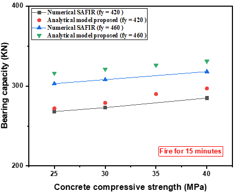
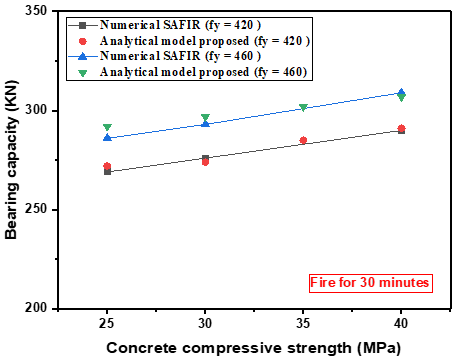
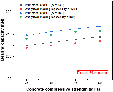
The study's findings indicate that the most effective reinforcing technique is steel plate jacketing. In this research, MATLAB software was utilized for curve fitting, employing polynomial functions to model errors. The metric used for assessment is R-squared, which is employed to establish a correlation between several factors, including the steel grade (Fy in kN/cm²), the cross-sectional area of the beam (A in cm²), the concrete compressive strength (Fc in kN/cm²). The analysis considered the load-bearing capacity after fire exposure (Pres in KN) and the load-bearing capacity after strengthening (Pstr in KN) as determined by the proposed SAFIR Finite Element Model (FEM). For load-bearing capacity after strengthening (Pstr), their properties are influenced by Fc, A, and Pres. A total of 36 data sets were generated using SAFIR FEM by varying parameters such as Fy, A, Fc, and Pres.
Figure 11. Effectiveness of post-fire beam rehabilitation techniques after different time periods
After collecting this data, a simplified equation was developed to calculate the new load-bearing capacity after strengthening (Pstr) in kilonewtons (KN). This equation is expressed as a function of the following variables: residual axial load-bearing capacity (Pres), Fy, Fc, and A. This equation likely represents the relationship between these variables, allowing for the calculation of the new load-bearing capacity after strengthening based on the given input values. This kind of analysis and equation development is common in structural engineering and materials science to understand the behavior of structures under various conditions and to optimize their performance. Shows this equation in Eq. (6).
$\mathrm{P}_{\text {str }}=\left(0.338471 \mathrm{~F}_{\mathrm{y}}+\mathrm{F}_{\mathrm{c}}\right) \times \frac{A}{80}+\mathrm{P}_{\text {res }}$ (6)
Furthermore, Figure 11 provides a visual representation of how various post-fire beam rehabilitation techniques perform after being exposed to fire for 15, 30, and 60 minutes. The results derived from Eq. (6) closely align with the numerical outcomes produced by the SAFIR software. Notably, the maximum recorded error between them did not surpass 5%, and the R-squared value between the two sets of data was calculated to be 0.687, as per Eq. (7).
$R$ squared $=1-(S S R / T S S)$ (7)
where, Calculate the total sum of squares (TSS) and the sum of squared residuals (SSR) utilizing the initial data and fitted values.
This paper examines post-fire damage to beams, with particular emphasis on a summary of current studies on the repair of post-fire concrete beams. To perform this analysis, a nonlinear finite element program, the SAFIR software, was used to explore the post-fire behavior of beams. This study emphasizes that the design of post-fire restoration necessitates the use of numerical tools equipped with appropriate models. Based on the results obtained and the discussions held, the following conclusions can be drawn:
(1) compared to the reference beam, the loss of load-bearing capacity was found to be 4.90%, 21.68%, 62.94%, and 85.31% for 15, 30, 60, and 90 minutes of heating time, respectively.
(2) The load-carrying capacity of beams after fire exposure decreases as the span of the beam increases.
(3) During a fire, the support conditions can significantly affect the bending moment and shear forces. The restraint beam show better performance.
(4) The strengthening method by BRP(V)-J provides the most reliable solution, it can improve the resistance of beams by 131.5%, 119.6% and 109.1% after exposure to fire for 15, 30 and 60 minutes, respectively. This technique can be considered as a promising material for the rehabilitation of concrete beams among the rehabilitation techniques proposed in this study.
(5) The repair of the reinforced concrete beam becomes ineffective after an hour of exposure to extreme temperatures and fire.
(6) A relationship between residual capacity ratios and temperature increase was established to estimate the residual capacity of fire-damaged beams. Additionally, a simplified equation was developed to calculate the load capacity of the strengthened beam and the proposed model agreed with the SAFIR software results,
This study contributes to the improvement and optimization of the choice of strengthening technique. Following the thermal damage and degradation of the mechanical behavior of beams after fire exposure. The results provide a database that will be useful for modeling the behavior of structural elements, allow a realistic assessment of the residual strength of concrete structures, and indicate potential implications for post-fire repair and design practice.
|
tpeak |
Time of exposure to fire, min |
|
T |
Temperature, ℃ |
|
N20℃ |
Load capacity in room temperature t=20℃, KN |
|
Ncollapse |
Load capacity in t C, KN |
|
Pu |
Load capacity during collapse, KN |
|
P (%) |
Reduction in load capacity, (%) |
|
Pres |
Load-bearing capacity residual after fire, KN |
|
Pstr |
Load-bearing capacity after strengthening, KN |
|
Δu |
Axial deformation at ultimate load, mm |
|
Fc |
Concrete compressive strength, KN/cm2 |
|
Fy |
Steel grade, KN/cm2 |
|
A |
Section, cm2 |
|
Subscripts |
|
|
RC |
Reinforced concrete |
|
FRP |
Fiber-Reinforced Polymer |
|
FEA |
Finite Element Analysis |
|
BRSC-J |
Repairing Steel Corner Jackets to concrete Beams |
|
BRS(V)-J |
Repairing Steel Vertical Jackets to concrete Beams |
|
BRS(H)-J |
Repairing Steel Horizontal Jackets to concrete Beams |
|
SSR |
Sum of Squared Residuals |
|
TSS |
Total Sum of Squares |
|
CJS |
Composite Jacket Strengthening |
[1] Aldhafairi, F., Hassan, A., Abd-EL-Hafez, L.M., Abouelezz, A.E.Y. (2020). Different techniques of steel jacketing for retrofitting of different types of concrete beams after elevated temperature exposure. Structures, 28: 713-725. https://doi.org/10.1016/j.istruc.2020.09.017
[2] Huang, Z. (2010). Modelling the bond between concrete and reinforcing steel in a fire. Engineering Structures, 32(11): 3660-3669. https://doi.org/10.1016/j.engstruct.2010.08.010
[3] Abdel-Hafez, L.M., Abouelezz, A.E.Y., Hassan, A.M. (2015). Behavior of RC columns retrofitted with CFRP exposed to fire under axial load. HBRC Journal, 11(1): 68-81. https://doi.org/10.1016/j.hbrcj.2014.02.002
[4] Hassan, A.M. (2013). Behavior of continuous flat slab exposed to fire. World Applied Sciences Journal, 23(6): 788-794.
[5] Hassan, A. (2013). Shape and size effects on concrete properties under an elevated temperature. Civil and Environmental Research, 3(7): 27-46.
[6] EN 1994-1-2. Eurocode 4, design of composite steel and concrete structures, part 1.2: General rules — structural fire design. Commission of the European Communities. Brussels: 2005. https://doi.org/10.3403/30111111
[7] EN 1992-1-2. Eurocode 2, design of concrete structures, part 1.2: General rules — structural fire design. Commission of the European Communities. Brussels: 2004. https://doi.org/10.3403/03213853
[8] Huang, Z., Burgess, I.W., Plank, R.J. (2004). 3D Modelling of beam-columns with general cross-sections in fire. In Paper S6-5, Third International Workshop on Structures in Fire, Ottawa, Canada, pp. 323-334.
[9] Huang, Z., Burgess, I.W., Plank, R.J. (2009). Three-dimensional analysis of reinforced concrete beam-column structures in fire. Journal of Structural Engineering, 135(10): 1201-1212. https://doi.org/10.1061/(asce)0733-9445(2009)135:10(1201)
[10] Qiu, J., Jiang, L., Usmani, A. (2021). Post-fire repair of concrete structural members: A review on fire conditions and recovered performance. International Journal of High-Rise Buildings, 10(4): 323-334. https://doi.org/10.21022/IJHRB.2021.10.4.323
[11] Kodur, V.K., Agrawal, A. (2016). Critical factors governing the residual response of reinforced concrete beams exposed to fire. Fire Technology, 52: 967-993. https://doi.org/10.1007/s10694-015-0527-5
[12] Akca, A.H., Özyurt, N. (2020). Post-fire mechanical behavior and recovery of structural reinforced concrete beams. Construction and Building Materials, 253: 119188. https://doi.org/10.1016/j.conbuildmat.2020.119188
[13] Jiang, C.J., Yu, J.T., Li, L.Z., Wang, X., Wang, L., Liao, J.H. (2018). Experimental study on the residual shear capacity of fire-damaged reinforced concrete frame beams and cantilevers. Fire Safety Journal, 100: 140-156. https://doi.org/10.1016/j.firesaf.2018.08.004
[14] ISO. (1999). ISO 834-1:1999 Fire-resistance tests - Elements of building construction – Part 1: General requirements, p. 25. https://doi.org/10.3403/30375031u
[15] Agrawal, A., Kodur, V. (2019). Residual response of fire-damaged high-strength concrete beams. Fire and Materials, 43(3): 310-322. https://doi.org/10.1002/fam.2702
[16] Thongchom, C., Lenwari, A., Aboutaha, R.S. (2019). Effect of sustained service loading on post-fire flexural response of reinforced concrete T-beams. ACI Structural Journal, 116(3): 243-254. https://doi.org/10.14359/51714477
[17] Yang, J., Yan, K., Doh, J.H., Zhang, X. (2023). Experimental study on shear performance of ultra-high-performance concrete beams at elevated temperatures. Engineering Structures, 291: 116304. https://doi.org/10.1016/j.engstruct.2023.116304
[18] Yan, K., Yang, J., Doh, J., Zhang, X. (2020). Factors governing the fire response of prestressed reactive powder concrete beams. Structural Concrete, 22(2): 607-22. https://doi.org/10.1002/suco.201900359
[19] Qin, H., Yang, J., Yan, K., Doh, J.H., Wang, K., Zhang, X. (2021). Experimental research on the spalling behaviour of ultra-high performance concrete under fire conditions. Construction and Building Materials, 303: 124464. https://doi.org/10.1016/j.conbuildmat.2021.124464
[20] Yan, K., Qin, H., Hu, Y., Yang, J., Doh, J.H., Zhang, X. (2022). Experimental and numerical studies on the fire resistance of prestressed reactive powder concrete beams. Structures, 45: 1814-1832. https://doi.org/10.1016/j.istruc.2022.10.006
[21] Xu, Z., Guo, X., Zhang, Y. (2005). Experiment on using CFRP to strengthen full-cale reinforced concrete beam after fire. Fire Safety Science, 14(1): 35-40.
[22] Zhang, Y., Xu, Z. (2009). Experimental on strengthening fire-damaged reinforced concrete beam with carbon fiber reinforced polymer. Journal of Natural Disasters, 18(1): 84-89.
[23] Irshidat, M.R., Al-Saleh, M.H. (2017). Flexural strength recovery of heat-damaged RC beams using carbon nanotubes modified CFRP. Construction and Building Materials, 145: 474-482. https://doi.org/10.1016/j.conbuildmat.2017.04.047
[24] Jadooe, A., Al-Mahaidi, R., Abdouka, K. (2017). Experimental and numerical study of strengthening of heat-damaged RC beams using NSM CFRP strips. Construction and Building Materials, 154: 899-913. https://doi.org/10.1016/j.conbuildmat.2017.07.202
[25] Jadooe, A., Al-Mahaidi, R., Abdouka, K. (2018). Behaviour of heat-damaged partially-insulated RC beams using NSM systems. Construction and Building Materials, 180: 211-228. https://doi.org/10.1016/j.conbuildmat.2018.05.279
[26] Jiang, C.J., Lu, Z.D., Li, L.Z. (2017). Shear performance of fire-damaged reinforced concrete beams repaired by a bolted side-plating technique. Journal of Structural Engineering, 143(5): 04017007. https://doi.org/10.1061/(ASCE)ST.1943-541X.000172
[27] Lamine, B.A., Mohamed, A., Rachid, R. (2023). Concrete reinforcement using composite fiberglass-based materials. The Journal of Engineering and Exact Sciences, 9(7): 16530-01e. https://doi.org/10.18540/jcecvl9iss7pp16530-01e
[28] Hassan, A., Aldhafairi, F., Abd-EL-Hafez, L.M., Abouelezz, A.E.Y. (2019). Retrofitting of different types of reinforced concrete beams after exposed to elevated temperature. Engineering Structures, 194: 420-430. https://doi.org/10.1016/j.engstruct.2019.05.084
[29] Belakhdar, A.R., Dimia, M.S., Baghdadi, M., Bouderradji, M., Gherabli, S., Alaoui, N. (2023). Post-fire behavior and repair of fire-damaged RC columns using composite jackets. Annales de Chimie - Science des Matériaux, 47(4): 247-257. https://doi.org/10.18280/acsm.470407
[30] Franssen, J.M., Gernay, T. (2017). Modeling structures in fire with SAFIR®: Theoretical background and capabilities. Journal of Structural Fire Engineering, 8(3): 300-323. https://doi.org/10.1108/JSFE-07-2016-0010
[31] Chaallal, O., Lachemi, M., Chaallal, O. (2011). Reinforced concrete structures: Design according to CSA A23.3-04. https://doi.org/10.1353/book15529
[32] Dwaikat, M.B., Kodur, V.K.R. (2009). Response of restrained concrete beams under design fire exposure. Journal of Structural Engineering, 135(11): 1408-1417. https://doi.org/10.1061/(ASCE)ST.1943-541X.0000058